Installation Guide ECL Comfort 210 / 310, application A214 / A314 1.0 Table of Contents 1.0 Table of Contents ............................................... 1 6.0 Common controller settings............................ 123 1.1 6.1 6.2 6.3 6.4 6.5 6.6 6.7 6.8 Important safety and product information. . . . . . . . . . . . . . . . . . . . . 2 2.0 Installation ........................................................ 4 2.1 2.2 2.3 2.4 2.5 2.6 2.7 2.8 Before you start . . . . . . . . . . . . . . . . . . .
Installation Guide ECL Comfort 210 / 310, application A214 / A314 1.1 Important safety and product information 1.1.1 Important safety and product information This Installation Guide is associated with ECL Application Key A214 (order code no. 087H3811). The A214 Key contains two sets of applications: one set (A214.1 / A214.2 / A214.3 / A214.4 / A214.5) and another set (A314.1 / A314.2 / A314.3).
Installation Guide ECL Comfort 210 / 310, application A214 / A314 This symbol indicates that this particular piece of information should be read with special attention. As this Installation Guide covers several system types, special system settings will be marked with a system type. All system types are shown in the chapter: 'Identifying your system type'. °C (degrees Celsius) is a measured temperature value whereas K (Kelvin) is a number of degrees. The ID no. is unique for the selected parameter.
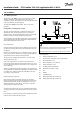
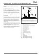
Installation Guide ECL Comfort 210 / 310, application A214 / A314 2.0 Installation 2.1 Before you start Typical A214.1 application: S1 Da nfos s 87H2113.10 The Application Key A214 contains several applications, mainly related to ventilation systems with heating or cooling or a combination of these. The applications in the A214 key offer a wide range of possibilities (see the examples). ECL 210 / (310) R4 (R6) The application A214.1 is very flexible.
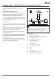
ECL Comfort 210 / 310, application A214 / A314 The application A214.2 is very flexible. These are the basic principles: Typical A214.2 application: S1 Heating with duct temperature control: Da nfos s 87H2118.10 Installation Guide ECL 210 / (310) R4 (R6) Typically, the heating temperature is adjusted according to your requirements. The flow temperature sensor S3 is the most important sensor. The desired temperature at S3 is set in the ECL Comfort controller as the 'Desired balance temperature'.
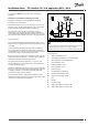
ECL Comfort 210 / 310, application A214 / A314 The application A214.3 is very flexible. These are the basic principles: Typical A214.3 application: S1 Heating with room temperature control: Da nfos s 87H2120.10 Installation Guide ECL 210 / (310) R4 (R6) Typically, the duct temperature is adjusted according to your requirements. The duct temperature sensor S3 is the most important sensor. The desired temperature at S3 is set in the ECL Comfort controller as the 'Desired balance temperature'.
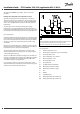
ECL Comfort 210 / 310, application A214 / A314 The application A214.4 is very flexible. These are the basic principles: Typical A214.4 application: S1 Da nfos s 87H2122.10 Installation Guide ECL 210 / (310) Heating and cooling with duct temperature control: R4 (R6) Typically, the heating and cooling temperature is adjusted according to your requirements. M1 The flow temperature sensor S3 in the heating circuit is the most important sensor.
ECL Comfort 210 / 310, application A214 / A314 The application A214.5 is very flexible. These are the basic principles: Typical A214.5 application: S1 Da nfos s 87H2124.10 Installation Guide ECL 210 / (310) Heating and cooling with room temperature control: R4 (R6) Typically, the heating and cooling temperature in the duct is adjusted according to your requirements. The duct temperature sensor S3 is the most important sensor.
ECL Comfort 210 / 310, application A214 / A314 The application A314.1 is very flexible. These are the basic principles: Typical A314.1 application: ECL 310 + ECA 32 S1 Heating and (passive) cooling with duct temperature control: Da nfos s 87H2133.10 Installation Guide R6 Typically, the heating and the cooling temperature is adjusted according to your requirements. M1 The flow temperature sensor S3 in the heating circuit is the most important sensor.
ECL Comfort 210 / 310, application A214 / A314 The application A314.2 is very flexible. These are the basic principles: Typical A314.2 application: S1 Heating and cooling with room temperature control: Da nfos s 87H2127.10 Installation Guide ECL 310 + ECA 32 R6 Typically, the heating and cooling temperature in the duct is adjusted according to your requirements. The duct temperature sensor S3 is the most important sensor.
ECL Comfort 210 / 310, application A214 / A314 The application A314.3 is very flexible. These are the basic principles: Typical A314.3 application: S1 Heating with room temperature control: Da nfos s 87H2131.10 Installation Guide ECL 310 + ECA 32 R6 Typically, the duct temperature is adjusted according to your requirements. The duct temperature sensor S3 is the most important sensor. The desired temperature at S3 is set in the ECL Comfort controller as the 'Desired balance temperature'.
Installation Guide ECL Comfort 210 / 310, application A214 / A314 A214 and A314 in general: Compensation temperature (optional): If the measured compensation temperature (S1 or S2) is higher or lower than the limitation value, the desired temperature at S3 can be adjusted. The compensation temperature can be measured by the outdoor temperature sensor or for example an additional room temperature sensor.
Installation Guide ECL Comfort 210 / 310, application A214 / A314 2.2 Identifying the system type Sketch your application The ECL Comfort controller series is designed for a wide range of heating, domestic hot-water (DHW) and cooling systems with different configurations and capacities. If your system differs from the diagrams shown here, you may want to make a sketch of the system about to be installed.
Installation Guide ECL Comfort 210 / 310, application A214 / A314 S1 Da nfos s 87H2114.10 A214.1 example b Ventilation system with cooling and constant room temperature control. Chiller has constant flow. ECL 210 / (310) R4 (R6) F1 S3 S4 S5 X3 M2 Setting advice: Set desired room temperature, for example 20 °C. Set desired balance temperature, for example 12 °C. If a room temperature sensor is not connected, the desired duct temperature at S3 will correspond to the desired room temperature.
Installation Guide ECL Comfort 210 / 310, application A214 / A314 S1 Da nfos s 87H2116.10 A214.1 example d Cooling system with constant flow temperature control ECL 210 / (310) R4 (R6) M2 S3 F1 Setting advice: Set desired room temperature, for example 1 °C. If a room temperature sensor is not connected, the desired flow temperature at S3 will correspond to the desired room temperature. Set ‘Fan cut-in delay’ (ID no. 11086 — ‘Settings’, ‘Fan / acc. control’) to 0 seconds. S1 Da nfos s 87H2117.
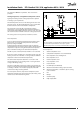
Installation Guide ECL Comfort 210 / 310, application A214 / A314 S1 Da nfos s 87H2118.10 A214.2 example a Ventilation system with heating and constant duct temperature control ECL 210 / (310) R4 (R6) M1 S3 S5 X3 P2 F1 S4 S6 S7 Sensor advice: Sensor S3 and S4 must be connected. If not, the fan (F1) stops, the damper (P2) and motorized control valve (M1) close. Navigation: Special settings for sensors / thermostats used as frost protection: ID no.
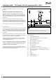
Installation Guide ECL Comfort 210 / 310, application A214 / A314 S1 ECL 210 / (310) Da nfos s 87H2119.10 A214.2 example b Heating of a swimming pool, constant water temperature control R4 (R6) S3 M1 S5 S4 F1 Sensor advice: Sensor S3 and S4 must be connected. If not, the pump (F1) stops and motorized control valve (M1) closes. Navigation: Special settings for sensors / thermostats used as frost protection: ID no.
Installation Guide ECL Comfort 210 / 310, application A214 / A314 S1 Da nfos s 87H2120.10 A214.3 example a Ventilation system with heating and constant room temperature control ECL 210 / (310) R4 (R6) M1 S5 X3 P2 F1 S3 S4 S6 S7 Setting advice: Set desired room temperature, for example 20 °C. Set desired balance temperature, for example 20 °C. If a room temperature sensor is not connected, the desired duct temperature at S3 will correspond to the desired room temperature.
Installation Guide ECL Comfort 210 / 310, application A214 / A314 S1 Da nfos s 87H2121.10 A214.3 example b Ventilation system (fan coils) with heating and constant room temperature control ECL 210 / (310) R4 (R6) F1 F1 S4 S3 X3 S5 M1 Setting advice: Set desired room temperature, for example 20 °C. Set desired balance temperature, for example 35 °C. If a room temperature sensor is not connected, the desired flow temperature at S3 will correspond to the desired room temperature.
Installation Guide ECL Comfort 210 / 310, application A214 / A314 S1 Da nfos s 87H2122.10 A214.4 example a Ventilation system with heating, cooling and constant duct temperature control ECL 210 / (310) R4 (R6) M1 S3 X3 M2 S5 P2 F1 S4 S6 S7 Sensor advice: Sensor S3 and S4 must be connected. If not, the fan (F1) stops, the damper (P2) and motorized control valves (M1 / M2) close. Navigation: Special settings for sensors / thermostats used as frost protection: ID no.
Installation Guide ECL Comfort 210 / 310, application A214 / A314 S1 Da nfos s 87H2123.10 A214.4 example b Ventilation system with heating, passive cooling (outside air) and constant duct temperature control ECL 210 / (310) R4 (R6) M1 S3 S5 X3 P2 M2 F1 S4 S6 S7 Sensor advice: Sensor S3 and S4 must be connected. If not, the fan (F1) stops, the damper (P2) and motorized control valves (M1 / M2) close. Navigation: Special settings for sensors / thermostats used as frost protection: ID no.
Installation Guide ECL Comfort 210 / 310, application A214 / A314 S1 Da nfos s 87H2124.10 A214.5 example a Ventilation system with heating, cooling and constant room temperature control ECL 210 / (310) R4 (R6) M1 X3 M2 S5 P2 F1 S3 S4 S6 S7 Setting advice: Set desired room temperature, for example 20 °C. Set desired balance temperature, for example 20 °C. If a room temperature sensor is not connected, the desired duct temperature at S3 will correspond to the desired room temperature.
Installation Guide ECL Comfort 210 / 310, application A214 / A314 S1 Da nfos s 87H2125.10 A214.5 example b Ventilation system with heating, passive cooling (outside air) and constant room temperature control ECL 210 / (310) R4 (R6) M1 S5 X3 P2 M2 F1 S3 S4 S6 S7 Setting advice: Set desired room temperature, for example 20 °C. Set desired balance temperature, for example 20 °C.
Installation Guide ECL Comfort 210 / 310, application A214 / A314 Da nfos s 87H2134.10 A214.5 example c Ventilation system with heating, cross-flow heat exchanger control and constant room temperature control ECL 210 / (310) S1 R4 / (R6) M1 S5 X3 P2 F1 S3 S4 S6 M2 S7 Setting advice: Set desired room temperature, for example 20 °C. Set desired balance temperature, for example 20 °C.
Installation Guide ECL Comfort 210 / 310, application A214 / A314 A314.1 example a Ventilation system with heating, passive cooling (outside air) and constant duct temperature control. Analog controlled passive cooling (M2). Da nfos s 87H2133.10 ECL 310 + ECA 32 S1 R6 M1 S3 S5 X3 P2 M2 A F1 S4 S6 S7 Sensor advice: Sensor S3 and S4 must be connected. If not, the fan (F1) stops, the damper (P2) and motorized control valves (M1 / M2) close.
Installation Guide ECL Comfort 210 / 310, application A214 / A314 Da nfos s 87H2128.10 A314.1 example b Ventilation system with heating, cooling and constant duct temperature control. Analog controlled cooling (M2). ECL 310 + ECA 32 S1 R6 M1 M2 A S3 X3 S5 P2 F1 S4 S6 S7 Sensor advice: Sensor S3 and S4 must be connected. If not, the fan (F1) stops, the damper (P2) and motorized control valves (M1 / M2) close.
Installation Guide ECL Comfort 210 / 310, application A214 / A314 S1 Da nfos s 87H2126.10 A314.1 example c Ventilation system with heating, passive cooling (outside air) and constant duct temperature control. Analog controlled speed of rotary heat exchanger (M2) for heat recovery. ECL 310 + ECA 32 R6 M1 S3 S5 X3 P2 F1 S4 S6 M2 S7 A Sensor advice: Sensor S3 and S4 must be connected. If not, the fan (F1) stops, the damper (P2) and motorized control valve (M1) close.
Installation Guide ECL Comfort 210 / 310, application A214 / A314 S1 Da nfos s 87H2127.10 A314.2 example a Ventilation system with heating, passive cooling (outside air) and constant room temperature control. Analog controlled passive cooling (M2). ECL 310 + ECA 32 R6 M1 S5 X3 P2 M2 A F1 S3 S4 S6 S7 Setting advice: Set desired room temperature, for example 20 °C. Set desired balance temperature, for example 20 °C.
Installation Guide ECL Comfort 210 / 310, application A214 / A314 Da nfos s 87H2135.10 A314.2 example b Ventilation system with heating, cooling and constant room temperature control. Analog controlled cooling (M2). ECL 310 + ECA 32 S1 R6 M1 M2 A X3 S5 P2 F1 S3 S4 S6 S7 Setting advice: Set desired room temperature, for example 20 °C. Set desired balance temperature, for example 20 °C.
Installation Guide ECL Comfort 210 / 310, application A214 / A314 S1 Da nfos s 87H2129.10 A314.2 example c Ventilation system with heating, passive cooling (outside air) and constant room temperature control. Analog controlled speed of rotary heat exchanger (M2) for heat recovery. ECL 310 + ECA 32 R6 M1 S5 X3 P2 F1 S3 S4 S6 M2 S7 A Setting advice: Set desired room temperature, for example 20 °C. Set desired balance temperature, for example 20 °C.
Installation Guide ECL Comfort 210 / 310, application A214 / A314 Da nfos s 87H2130.10 A314.2 example d Ventilation system with heating, analog controlled cross-flow heat exchanger (M2) and constant room temperature control ECL 310 + ECA 32 S1 R6 M1 S5 X3 P2 F1 S3 S4 S6 M2 A S7 Setting advice: Set desired room temperature, for example 20 °C. Set desired balance temperature, for example 20 °C.
Installation Guide ECL Comfort 210 / 310, application A214 / A314 S1 Da nfos s 87H2131.10 A314.3 example a Ventilation system with heating and constant room temperature control. Analog controlled fan speed (V1) based on outdoor wind speed. ECL 310 + ECA 32 R6 M1 S10 S5 X3 P2 F1 / V1 S3 S4 S6 S7 Setting advice: Set desired room temperature, for example 20 °C. Set desired balance temperature, for example 35 °C.
Installation Guide ECL Comfort 210 / 310, application A214 / A314 S1 Da nfos s 87H2132.10 A314.3 example b Ventilation system with heating and constant room temperature control. Analog controlled air curtain (V1) speed based on outdoor wind speed. ECL 310 + ECA 32 R6 V1 A M1 S10 S5 X3 P2 F1 S3 S4 S6 S7 Setting advice: Set desired room temperature, for example 20 °C. Set desired balance temperature, for example 35 °C.
Installation Guide ECL Comfort 210 / 310, application A214 / A314 2.3 Mounting 2.3.1 Mounting the ECL Comfort controller For easy access, you should mount the ECL Comfort controller near the system. Select one of the following methods using the same base part (code no. 087H3220 (ECL Comfort 210) or 087H3230 (ECL Comfort 310): • Mounting on a wall • Mounting on a DIN rail (35 mm) The ECL Comfort 210 can be mounted in the ECL Comfort 210 / 310 base part.
Installation Guide ECL Comfort 210 / 310, application A214 / A314 Mounting on a wall Mount the base part on a wall with a smooth surface. Establish the electrical connections and position the controller in the base part. Secure the controller with the locking pin. Mounting on a DIN rail (35 mm) Mount the base part on a DIN rail. Establish the electrical connections and position the controller in the base part. Secure the controller with the locking pin.
Installation Guide ECL Comfort 210 / 310, application A214 / A314 2.3.2 Mounting the Remote Control Units ECA 30/31 Select one of the following methods: • Mounting on a wall, ECA 30 / 31 • Mounting in a panel, ECA 30 Screws and rawlplugs are not supplied. Mounting on a wall Mount the base part of the ECA 30 / 31 on a wall with a smooth surface. Establish the electrical connections. Place the ECA 30 / 31 in the base part.
Installation Guide ECL Comfort 210 / 310, application A214 / A314 2.4 Placing the temperature sensors 2.4.1 Placing the temperature sensors It is important that the sensors are mounted in the correct position in your system.
Installation Guide ECL Comfort 210 / 310, application A214 / A314 Pt 1000 temperature sensor (IEC 751B, 1000 Ω / 0 °C) Relationship between temperature and ohmic value: Ω °C Ω -50 -40 -30 -20 -10 0 10 20 30 40 50 60 70 80 90 100 110 120 130 140 150 803 843 882 922 961 1000 1039 1078 1117 1155 1194 1232 1271 1309 1347 1385 1423 1461 1498 1535 1573 1600 1500 1400 1300 1200 1100 1000 900 800 °C -50 38 DEN-SMT/DK VI.GU.A1.
Installation Guide ECL Comfort 210 / 310, application A214 / A314 2.5 Electrical connections 2.5.1 Electrical connections 230 V a.c. in general The common ground terminal is used for connection of relevant components (pumps, motorized control valves). Danfoss District Energy VI.GU.A1.
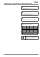
Installation Guide ECL Comfort 210 / 310, application A214 / A314 2.5.2 Electrical connections, 230 V a.c., power supply, pumps, motorized control valves etc. In general, the drawing and description below apply to all A214 applications. However, please note that: A214.1 is without M1 A214.2 / A214.3 are without M2 Terminal 16 15 14 Description Max. load Alarm 4 (2) A / 230 V a.c.* Phase for control of connected units 13 X3 Circulation pump ON / OFF 4 (2) A / 230 V a.c.
Installation Guide ECL Comfort 210 / 310, application A214 / A314 Da nfos s 87H2136.10 A314: Terminal 19 18 R6 Description Phase for alarm output Max. load Alarm 4 (2) A / 230 V a.c.* 17 Not to be used 16 Not to be used 15 14 Not to be used Phase for control of connected units 13 X3 Circulation pump ON / OFF 4 (2) A / 230 V a.c.* 12 P2 Damper ON / OFF 4 (2) A / 230 V a.c.* 11 F1 Fan / pump ON / OFF 4 (2) A / 230 V a.c.* 10 Supply voltage 230 V a.c.
Installation Guide ECL Comfort 210 / 310, application A214 / A314 2.5.3 Electrical connections, safety thermostats, 230 V a.c. or 24 V a.c. Da nfos s 87H2105.10 With safety thermostat, 1–step closing: Motorized control valve without safety function ECL 210 / 310 Da nfos s 87H2106.10 M1 ECL 210 / 310 M2 Da nfos s 87H2107.10 With safety thermostat, 1–step closing: Motorized control valve with safety function ECL 210 / 310 M1 42 DEN-SMT/DK VI.GU.A1.
Installation Guide ECL Comfort 210 / 310, application A214 / A314 Da nfos s 87H2108.10 ECL 210 / 310 M2 With safety thermostat, 2–step closing: Motorized control valve with safety function Da nfos s 87H2109.10 ECL 210 / 310 M1 Da nfos s 87H2110.10 ECL 210 / 310 M2 When ST is activated by a high temperature, the safety circuit in the motorized control valve closes the valve immediately.
Installation Guide ECL Comfort 210 / 310, application A214 / A314 Wire cross section: 0.5 - 1.5 mm² Incorrect connection can damage the electronic outputs. Max. 2 x 1.5 mm² wires can be inserted into each screw terminal. 44 DEN-SMT/DK VI.GU.A1.
Installation Guide ECL Comfort 210 / 310, application A214 / A314 2.5.4 Electrical connections, 24 V a.c., power supply, pumps, motorized valves etc. In general, the drawing and description below apply to all A214 applications. However, please note that: A214.1 is without M1 A214.2 / A214.3 are without M2 Terminal 16 15 14 Description Max. load Alarm 4 (2) A / 24 V a.c.* Phase for control of connected units 13 R3 (K3) Circulation pump ON / OFF 4 (2) A / 24 V a.c.
Installation Guide ECL Comfort 210 / 310, application A214 / A314 Do not connect 230 V a.c. powered components to a 24 V a.c. power supplied controller directly. Use auxilliary relays (K) to seperate 230 V a.c. from 24 V a.c. 46 DEN-SMT/DK VI.GU.A1.
Installation Guide ECL Comfort 210 / 310, application A214 / A314 Da nfos s 87H2137.10 A314: Terminal 19 18 R6 Description Phase for alarm output Max. load Alarm 4 (2) A / 24 V a.c.* 17 Not to be used 16 Not to be used 15 14 Not to be used Phase for control of connected units 13 R3 (K3) Circulation pump ON / OFF 4 (2) A / 24 V a.c.* 12 R2 (K2) Damper ON / OFF 4 (2) A / 24 V a.c.* 11 R1 (K1) Fan / pump ON / OFF 4 (2) A / 24 V a.c.* 10 Supply voltage 24 V a.c.
Installation Guide ECL Comfort 210 / 310, application A214 / A314 Do not connect 230 V a.c. powered components to a 24 V a.c. power supplied controller directly. Use auxilliary relays (K) to seperate 230 V a.c. from 24 V a.c. 48 DEN-SMT/DK VI.GU.A1.
Installation Guide ECL Comfort 210 / 310, application A214 / A314 A314— ECA 32: Double-insulated (two-chamber) transformer Terminal Description Max. load 49 Common terminal (connected to terminal 30 in the ECL Comfort controller) 56 Analog reference for Analog Out 2 and 3 57 Not to be used 58 Not to be used 59 M2 Analog Out 1 60 Analog Out 2 (not used) 61 62 Analog Out 3 (not used) 47 kΩ* Analog reference for Analog Out 1 * The value must be 47 kΩ as a minimum. Wire cross section: 0.
Installation Guide ECL Comfort 210 / 310, application A214 / A314 2.5.5 Electrical connections, Pt 1000 temperature sensors and signals A214/ A314: Terminal Sensor / description 29 and 30 S1 28 and 30 S2 27 and 30 S3 26 and 30 S4 25 and 30 S5 24 and 30 S6 23 and 30 S7 22 and 30 S8 21 and 30 20 and 30 Type (recomm.
Installation Guide ECL Comfort 210 / 310, application A214 / A314 Connection of frost thermostats, S7 When frost (too low temperature) is detected, contacts 1-2 close. When frost (too low temperature) is detected, contacts 1-4 open. Connection of fire thermostats, S8 When fire (too high temperature) is detected, the contacts 1-4 close. When fire (too high temperature) is detected, the contacts 1-2 open. Danfoss District Energy VI.GU.A1.
Installation Guide ECL Comfort 210 / 310, application A214 / A314 Wire cross section for sensor connections: Min. 0.4 mm². Total cable length: Max. 200 m (all sensors incl. internal ECL 485 communication bus) Cable lengths of more than 200 m may cause noise sensibility (EMC). 52 DEN-SMT/DK VI.GU.A1.
Installation Guide ECL Comfort 210 / 310, application A214 / A314 Terminal Terminal ECL ECA 30 / 31 4 30 31 1 32 2 33 3 4 5 Description Type (recomm.) ECA 30 / 31 ECL 210 / 310 Da nfos s 87H2051.10 2.5.6 Electrical connections, ECA 30 / 31 Twisted pair Cable 2 x twisted pair Twisted pair Ext. room temperature sensor* B ESM-10 A B ESM-10 * After an external room temperature sensor has been connected, ECA 30 / 31 must be repowered.
Installation Guide ECL Comfort 210 / 310, application A214 / A314 2.5.7 Electrical connections, master / slave systems Da nfos s 87H2052.10 The controller can be used as master or slave in master / slave systems via the internal ECL 485 communication bus (2 x twisted pair cable).
Installation Guide ECL Comfort 210 / 310, application A214 / A314 Electrical connections, Modbus ECL 210 / 310 Da nfos s 87H2060.10 2.5.8 Electrical connections, communication B A B Electrical connections, M-bus Da nfos s 87H2061.10 A ECL 310 B A B A Danfoss District Energy VI.GU.A1.
Installation Guide ECL Comfort 210 / 310, application A214 / A314 2.6 Inserting the ECL Application Key 2.6.1 Inserting the ECL Application Key This section describes the function in general for the ECL Comfort 210 / 310 series and is not application related. The ECL Application Key contains • the application and its subtypes, • currently available languages, • factory settings: e.g. schedules, desired temperatures, limitation values etc.
Installation Guide ECL Comfort 210 / 310, application A214 / A314 Automatic update of controller software: The software of the controller is updated automatically when the key is inserted (as of controller version 1.11). The following animation will be shown when the software is being updated: Progress bar During update: - Do not remove the KEY - Do not disconnect the power Danfoss District Energy VI.GU.A1.
Installation Guide ECL Comfort 210 / 310, application A214 / A314 Application Key: Situation 1 The controller is new from the factory, the ECL Application Key is not inserted. An animation for the ECL Application Key insertion is displayed. Insert the Application Key . Application Key name and Version is indicated (example: A266 Ver. 1.03). If the ECL Application Key is not suitable for the controller, a "cross" is displayed over the ECL Application Key-symbol.
Installation Guide ECL Comfort 210 / 310, application A214 / A314 Application Key: Situation 2 The controller already runs an application. The ECL Application Key is inserted, but the application needs to be changed. To change to another application on the ECL Application Key, the current application in the controller must be erased (deleted). Be aware that the Application Key must be inserted.
Installation Guide ECL Comfort 210 / 310, application A214 / A314 Application Key: Situation 3 A copy of the controllers settings is needed for configuring another controller. This function is used • for saving (backup) of special user and system settings • when another ECL Comfort controller of the same type (210 or 310) must be configured with the same application but user / system settings differ from the factory settings.
Installation Guide ECL Comfort 210 / 310, application A214 / A314 2.6.2 ECL Application Key, copying data General principles When the controller is connected and operating, you can check and adjust all or some of the basic settings. The new settings can be stored on the Key. Factory settings can always be restored. How to update the ECL Application Key after settings have been changed? All new settings can be stored on the ECL Application Key.
Installation Guide ECL Comfort 210 / 310, application A214 / A314 2.7 Check list Is the ECL Comfort controller ready for use? Make sure that the correct power supply is connected to terminals 9 (Live) and 10 (Neutral). Check that the required controlled components (actuator, pump etc.) are connected to the correct terminals. Check that all sensors / signals are connected to the correct terminals (see 'Electrical connections'). Mount the controller and switch on the power.
Installation Guide ECL Comfort 210 / 310, application A214 / A314 2.8 Navigation, ECL Application Key A214 / A314 Navigation, A214, applications A214.1, A214.2, A214.3, A214.4 and A214.5 Home Applications A214 MENU ID no. Schedule Settings A214.1 A214.2 A214.3 A214.4 A214.5 Selectable Flow temperature Room limit Duct T limit Return limit Limit T safety 11008 Desired balance T ( ( ( ( ( 11178 Temp. max. ( ( ( ( ( 11177 Temp. min.
Installation Guide ECL Comfort 210 / 310, application A214 / A314 Navigation, A214, applications A214.1, A214.2, A214.3, A214.4 and A214.5 continued Home Applications, A214 MENU Settings Control par. 2 Fan / acc. control Application 64 DEN-SMT/DK A214.4 A214.5 Motor pr. ( ( 12184 Xp ( ( 12185 Tn ( ( 12186 M run ( ( 12187 Nz ( ( 12189 Min. act. time ( ( 11088 Fan output func.
Installation Guide ECL Comfort 210 / 310, application A214 / A314 Navigation, A214, applications A214.1, A214.2, A214.3, A214.4 and A214.5 continued Home Applications A214 MENU ID no. Holiday Alarm Function A214.1 A214.2 A214.3 A214.4 A214.
Installation Guide ECL Comfort 210 / 310, application A214 / A314 Navigation, A214, applications A214.1, A214.2, A214.3, A214.4 and A214.5, Common controller settings Home Applications A214, Common controller settings MENU ID no. A214.1 Function A214.2 A214.3 A214.
Installation Guide ECL Comfort 210 / 310, application A214 / A314 Navigation, A214, applications A214.1, A214.2, A214.3, A214.4 and A214.5, Common controller settings, continued Home Applications A214, Common controller settings MENU Key functions ID no. New application A214.1 A214.2 A214.3 A214.4 A214.
Installation Guide ECL Comfort 210 / 310, application A214 / A314 Navigation, A314, applications A314.1, 314.2 and A314.3 Home Application A314 MENU ID no. Schedule Settings Flow temperature Duct T limit Return limit Limit T safety A314.2 A314.3 11008 Desired balance T ( ( ( 11178 Temp. max. ( ( ( 11177 Temp. min. ( ( ( 11009 Dead zone ( ( 11182 Infl. - max. ( ( 11183 Infl. - min. ( ( 11015 Adapt. time ( ( 11182 Infl. - max. ( 11183 Infl. - min.
Installation Guide ECL Comfort 210 / 310, application A214 / A314 Navigation, A314, applications A314.1, A314.2 and A314.3 Home Applications A314 MENU Settings Control par. 2 ID no. Function A314.1 A314.2 12174 Motor pr. ( ( 12184 Xp ( ( 12185 Tn ( ( 12186 M run ( ( 12187 Nz ( ( 12189 Min. act. time ( ( 12165 V out max. ( ( 12167 V out min. ( ( 12171 Reverse out ( ( Fan / acc. control 11081 Application Danfoss District Energy A314.
Installation Guide ECL Comfort 210 / 310, application A214 / A314 Navigation, A314, applications A314.1, A314.2 and A314.3 continued Home Applications A314 MENU ID no. Holiday Alarm A314.1 A314.2 A314.
Installation Guide ECL Comfort 210 / 310, application A214 / A314 Navigation, A314, applications A314.1, A314.2, A314.3, A314.4 and A314.5, Common controller settings Home Applications A314, Common controller settings MENU ID no. Function A314.1 A314.2 A314.
Installation Guide ECL Comfort 210 / 310, application A214 / A314 Navigation, A314, applications A314.1, A314.2, A314.3 and A314.4, Common controller settings, continued Home Applications A314, Common controller settings MENU Key functions ID no. New application Function Copy ( ( ( ( System settings ( ( ( User settings ( ( ( Go to factory ( ( ( To ( ( ( System settings ( ( ( User settings ( ( ( ( ( ( ( ( ( Code no.
Installation Guide ECL Comfort 210 / 310, application A214 / A314 3.0 Daily use 3.1 How to navigate This section describes the function in general for the ECL Comfort 210 / 310 series and is not application related. You navigate in the controller by turning the dial left or right to the desired position ( ). The dial has a built-in accellerator. The faster you turn the dial, the faster it reaches the limits of any wide setting range.
Installation Guide ECL Comfort 210 / 310, application A214 / A314 3.2 Understanding the controller display This section describes the function in general for the ECL Comfort 210 / 310 series. The shown displays are typical and not application related. They might differ from the displays in your application. Choosing a favorite display Your favorite display is the display you have chosen as the default display.
Installation Guide ECL Comfort 210 / 310, application A214 / A314 If the temperature value is displayed as "- -" the sensor in question is not connected. "- - -" the sensor connection is short-circuited. Setting the desired temperature Depending on the chosen circuit and mode, it is possible to enter all daily settings directly from the overview displays (see also the next page concerning symbols).
Installation Guide ECL Comfort 210 / 310, application A214 / A314 3.3 A general overview: What do the symbols mean? Symbol Description Symbol Description Sensor not connected or not used Outdoor temp. Sensor connection short-circuited Room temp. Temperature 7-23 Fixed comfort day (holiday) DHW temp.
Installation Guide ECL Comfort 210 / 310, application A214 / A314 3.4 Monitoring temperatures and system components This section describes the function in general for the ECL Comfort 210 / 310 series. The shown displays are typical and not application related. They might differ from the displays in your application. Heating circuit The overview display in the heating circuit ensures a quick overview of the actual and (desired) temperatures as well as the actual state of the system components.
Installation Guide ECL Comfort 210 / 310, application A214 / A314 3.5 Influence overview This section describes the function in general for the ECL Comfort 210 / 310 series. The shown displays are typical and not application related. They might differ from the displays in your application. The menu gives an overview of the influences on the desired flow temperature. It differs from application to application which parameters are listed.
Installation Guide ECL Comfort 210 / 310, application A214 / A314 3.6 Manual control This section describes the function in general for the ECL Comfort 210 / 310 series. The shown displays are typical and not application related. They might differ from the displays in your application. It is possible to manually control the installed components. Manual control can only be selected in favorite displays in which the symbols for the controlled components (valve, pump etc.) are visible.
Installation Guide ECL Comfort 210 / 310, application A214 / A314 3.7 Schedule 3.7.1 Set your schedule This section describes the schedule in general for the ECL Comfort 210 / 310 series. The shown displays are typical and not application related. They might differ from the displays in your application. In some applications, however, there might be more than one schedule. Additional schedules can be found in ‘Common controller settings’.
Installation Guide ECL Comfort 210 / 310, application A214 / A314 4.0 Settings overview It is recommendable to make a note of any changed settings in the empty columns. Setting ID Factory settings in circuit(s) Page 1 Desired balance T 11008 84 20 °C Desired balance T — A214.1 Temp. max. (flow / duct temp. limit, max.) — A214 / A314 in general Temp. max. (flow / duct temp. limit, max.) — A214.1 11008 84 20 °C 11178 84 40 °C 11178 84 40 °C Temp. max. (flow / duct temp. limit, max.
Installation Guide ECL Comfort 210 / 310, application A214 / A314 Setting ID Factory settings in circuit(s) Page 1 Min. act. time (min. activation time gear motor) 12189 101 10 V out max. — A314.1 / A314.2 12165 102 100% V out min. — A314.1 / A314.2 12167 103 0% Reverse out — A314.1 / A314.2 12171 103 ON Fan output func. (relay 1, F1) 11088 104 1 Fan cut-in delay (relay 1, F1) 11086 104 30 s Fan cut-in delay (relay 1, F1) — A214.
Installation Guide Setting ECL Comfort 210 / 310, application A214 / A314 ID Factory settings in circuit(s) Page 1 Lowest temp. 11150 Alarm overview, in general 122 2 3 30 °C 122 Backlight (display brightness) 60058 132 5 Contrast (display contrast) 60059 132 3 Modbus addr. 38 133 1 ECL 485 addr. (master / slave address) 2048 133 15 Service Pin 2150 133 0 Ext. reset 2151 134 0 Language 2050 134 English Danfoss District Energy VI.GU.A1.
Installation Guide ECL Comfort 210 / 310, application A214 / A314 5.0 Settings, applications A214 / A314 5.1 Flow temperature The temperature, measured by S3, can be a flow or a duct temperature. The desired temperature at S3 is the desired balance temperature, ‘Desired balance T’. 11008 Desired balance T Circuit Setting range Factory setting 1 5 ... 110 °C 20 °C In all applications, the S3 temperature sensor is the most important sensor and must always be connected.
Installation Guide ECL Comfort 210 / 310, application A214 / A314 Temp. min. (flow / duct temp. limit, min.) 11177 Circuit Setting range Factory setting 1 5 ... 150 °C 10 °C Set the min. flow / duct temperature for the system. The desired temperature at S3 will not be lower than this setting. Adjust the factory setting, if required. Temp. min. (flow / duct temp. limit, min.) — A214.1 The setting for ‘Temp. max.’ has higher priority than ‘Temp. min.’. The setting of 'Temp. min.
Installation Guide ECL Comfort 210 / 310, application A214 / A314 5.2 Room limit This section is only relevant if the A214 application works with room temperature signal (a room temperature sensor or a Remote Control Unit) is used. The applications are: A214.1, A214.3, A214.5, A314.2 and A314.3. Influence ‘Infl. - min.’ (min.
Installation Guide ECL Comfort 210 / 310, application A214 / A314 11183 Infl. - min. (room temp. limitation, min.) Circuit Setting range Factory setting 1 0.0 ... 30.0 2.0 Determines how much the desired flow / duct temperature at S3 will be influenced (increased) if the actual room temperature is lower than the desired room temperature (P control). 0.0: The room temperature has no influence. 2.0: The room temperature has a minor influence. 30.0: The room temperature has a big influence.
Installation Guide ECL Comfort 210 / 310, application A214 / A314 5.3 Duct T limit This section is only relevant for A214 applications without room temperature control. The applications are: A214.2, A214.4 and A314.1. 11182 Infl. - max. (duct temp. limitation, max.) Circuit Setting range Factory setting 1 –30.0 ... 0.0 -2.0 Determines how much the desired flow temperature at S3 will be influenced (decreased) if the actual duct temperature is higher than the desired duct temperature (P control).
Installation Guide ECL Comfort 210 / 310, application A214 / A314 5.4 Return limit This section describes the function in general for the ECL Comfort 210 / 310 series. The shown displays are typical and not application related. They might differ from the displays in your application. The return temperature limitation is based on a constant temperature value. Influence ‘Infl. - min.
Installation Guide ECL Comfort 210 / 310, application A214 / A314 Infl. - max. (return temp. limitation - max. influence) 11035 Circuit Setting range Factory setting 1 -9.9 ... 9.9 0.0 Determines how much the desired flow temperature will be influenced if the return temperature is higher than the calculated limit. Influence higher than 0: The desired flow temperature is increased, when the return temperature gets higher than the calculated limit.
Installation Guide ECL Comfort 210 / 310, application A214 / A314 5.5 Limit T safety The temperature sensor S5 can, besides operating as return temperature limitation sensor, act as frost protection sensor. When the S5 temperature becomes lower than the set value, the desired flow temperature will be increased (the motorized control valve opens gradually). The influence can be set. 11108 Limit T frost (sliding frost protection) Circuit Setting range Factory setting 1 OFF / 0 ...
Installation Guide ECL Comfort 210 / 310, application A214 / A314 5.6 Compensation 1 The desired flow / duct temperature can be influenced by a compensation temperature, measured by S1 or S2. The choice between S1 and S2 is made by means of a set-up menu. The following describes the compensation by means of S1. The desired flow temperature can be influenced by a compensation temperature, measured by S1.
Installation Guide ECL Comfort 210 / 310, application A214 / A314 11061 Adapt. time (adaptation time) Circuit Setting range Factory setting 1 OFF / 1 ... 50 s OFF The adaptation function can correct the desired flow temperature with max. 8 K. Controls how fast the compensation temperature influences the desired flow temperature. OFF: 1: The control function is not influenced by the ‘Adapt. time’. The desired flow temperature is adapted quickly.
Installation Guide ECL Comfort 210 / 310, application A214 / A314 5.7 Compensation 2 This extra compensation temperature setting makes it possible to change the desired flow temperature in relation to a second limitation point. 11064 Limit (compensation temp., 2. point) Circuit Setting range Factory setting 1 –20 ... 80 °C 25 °C Influence + Set the compensation temperature limit point 2.
Installation Guide ECL Comfort 210 / 310, application A214 / A314 11065 Adapt. time (adaptation time) Circuit Setting range Factory setting 1 OFF / 1 ... 50 s OFF The adaptation function can correct the desired flow temperature with max. 8 K. Controls how fast the compensation temperature influences the desired flow temperature. OFF: 1: The control function is not influenced by the ‘Adapt. time’. The desired flow temperature is adapted quickly.
Installation Guide ECL Comfort 210 / 310, application A214 / A314 Combination of two compensation temperature limit points: Compensation 1 and 2 can be combined to give a compensation at 2 different compensation temperatures. This can for instance be used to avoid a too big difference between the indoor and outdoor temperatures. Regarding compensation temperatures, example 1 shows that below Comp. 1 and above Comp. 2, the desired flow temperature will be increased, but with different values.
Installation Guide ECL Comfort 210 / 310, application A214 / A314 5.8 Control parameters (1) 11174 Motor pr. (motor protection) Circuit Setting range Factory setting 1 OFF / 10 ... 59 m OFF Recommended for duct systems with variable load. Prevents the controller from unstable temperature control (and resulting actuator oscillations). This can occur at very low load. The motor protection increases the lifetime of all involved components. OFF: Motor protection is not activated. 10 ...
Installation Guide ECL Comfort 210 / 310, application A214 / A314 11187 Nz (neutral zone) Circuit Setting range Factory setting 1 1 ... 9 K 3K The neutral zone is symmetrical around the desired flow / duct temperature value, i.e. half the value is above and half the value is below this temperature. Set the acceptable flow /duct temperature deviation. Set the neutral zone to a high value if you can accept a high variation in flow temperature.
Installation Guide ECL Comfort 210 / 310, application A214 / A314 If you want to tune the PI regulation precisely, you can use the following method: • Set the ‘Tn’ (integration time constant) to its max. value (999 sec.). • Decrease the value for the ‘Xp’ (proportional band) until the system starts hunting (i.e. gets unstable) with a constant amplitude (it might be necessary to force the system by setting an extreme low value).
Installation Guide ECL Comfort 210 / 310, application A214 / A314 5.9 Control parameters (2) 12174 Motor pr. (motor protection) Circuit Setting range Factory setting 1 OFF / 10 ... 59 m OFF Prevents the controller from unstable temperature control (and resulting actuator oscillations). This can occur at very low load. The motor protection increases the lifetime of all involved components. OFF: Motor protection is not activated. 10 ...
Installation Guide ECL Comfort 210 / 310, application A214 / A314 12187 Nz (neutral zone) Circuit Setting range Factory setting 1 1 ... 9 K 3K The neutral zone is symmetrical around the desired flow / duct temperature value, i.e. half the value is above and half the value is below this temperature. Set the acceptable flow / duct temperature deviation. Set the neutral zone to a high value if you can accept a high variation in flow / duct temperature.
Installation Guide ECL Comfort 210 / 310, application A214 / A314 If you want to tune the PI regulation precisely, you can use the following method: • Set the ‘Tn’ (integration time constant) to its max. value (999 sec.). • Decrease the value for the ‘Xp’ (proportional band) until the system starts hunting (i.e. gets unstable) with a constant amplitude (it might be necessary to force the system by setting an extreme low value).
Installation Guide ECL Comfort 210 / 310, application A214 / A314 12167 V out min. — A314.1 / A314.2 Circuit Setting range Factory setting 1 0 ... 100% 0% The output voltage can be limited to a minimum value. Example: A setting of 20% means that the output voltage will be 2 volt as a minimum. 0 ... 100: The value in % expresses the minimum voltage for controlling the output for the M2 actuator. The setting 'Reverse out' has no influence on the 'V out max’ or ‘V out min' settings.
Installation Guide ECL Comfort 210 / 310, application A214 / A314 5.10 Fan / acc. control (fan / accessory control) This section describes the functions for relay 1 (F1), relay 2 (P2) and relay 3 (X3). 11088 Fan output func. (relay 1, F1) Circuit Setting range Factory setting 1 0 ... 3 1 Desired function for relay 1 (F1). F1 is typically the fan. The codes have different meanings. Code: Example, code = 1: The fan is ON during Comfort mode. In case of frost alarm, the fan is switched OFF.
Installation Guide ECL Comfort 210 / 310, application A214 / A314 11137 Fan function (relay 1, F1) — A214.1 Circuit Setting range Factory setting 1 OFF / ON OFF In this cooling application, the fan can remain switched ON even if saving mode is active. OFF: The fan is switched OFF during saving mode. ON: The fan is switched ON also during saving mode. 11137 Fan function (relay 1, F1) — A214.2 / A214.
Installation Guide ECL Comfort 210 / 310, application A214 / A314 11089 Acc. output func. (relay 2, P2) Circuit Setting range Factory setting 1 0 ... 3 1 Desired function for relay 2 (P2). P2 is typically the damper. The codes have different meanings. Code: Example, code = 1: The damper is open (switched ON) during Comfort mode. In case of frost alarm, the damper is closed (switched OFF).
Installation Guide ECL Comfort 210 / 310, application A214 / A314 11090 Optional function (relay 3, X3)— A214.2 Circuit Setting range Factory setting 1 0, 1, 2 0 Desired function for relay 3 (X3). The codes have different meanings. Description: Code: 0 Control of circulation pump in heating circuit 1 Follows schedule 1 2 Follows schedule 2 11090 Optional function (relay 3, X3)— A214.3 / A314.3 Circuit Setting range Factory setting 1 0, 1, 2, 3 0 Desired function for relay 3 (X3).
Installation Guide ECL Comfort 210 / 310, application A214 / A314 11077 P frost T (pump frost protection temperature) Circuit Setting range Factory setting 1 OFF / -10 ... 20 °C 2 °C Frost protection, based on the outdoor temperature: When the outdoor temperature is below the set temperature in ‘P frost T’, the controller automatically switches ON circulation pump X3 to protect the system.
Installation Guide ECL Comfort 210 / 310, application A214 / A314 A314.3: Wind influence on fan speed A wind speed sensor can be connected to the ECL controller in order to control the fan speed. Typically, the more windy, the higher the fan speed. The signal from the wind speed sensor is a 0-10 volt signal which is applied directly to input S10. The voltage rises at higher wind speed. The measured voltage on input S10 must be converted to a wind speed value by the controller.
Installation Guide ECL Comfort 210 / 310, application A214 / A314 Control voltage Circuit Setting range 1 0.0 ... 10.0 V Factory setting Output voltage in relation to measured wind speed. The measured and converted wind speed signal controls the output signal 'Control voltage'. Typically, the higher the wind speed, the higher the 'control voltage' for the fan speed. Push the dial to see the graph and enter the value sets for the wind speed values (0 and 10 m/s) and control voltage.
Installation Guide ECL Comfort 210 / 310, application A214 / A314 5.11 Application Depending on application type (heating and / or cooling), the mentioned flow temperature in this section can either be a flow or a duct temperature. 11010 ECA addr. (choice of Remote Control Unit) — A214.1 / A214.3 / A214.5 / A314.2 / A314.3 Circuit Setting range Factory setting 1 OFF / A / B OFF The Remote Control Unit must be set accordingly (A or B).
Installation Guide ECL Comfort 210 / 310, application A214 / A314 11021 Total stop Circuit Setting range Factory setting 1 OFF / ON OFF The examples below are related to heating applications: Desired flow temp. °C Total stop = ON Setting the 'Total stop' to OFF or ON gives different results, depending on the actual application. The conditions are: - Room temperature controlled applications - Total stop during the saving temperature period OFF: ‘Frost pr.’ Time No total stop.
Installation Guide ECL Comfort 210 / 310, application A214 / A314 Total stop, examples: Total stop OFF — A214.2 / A214.4 / A314.1 A214.2 / A214.4 / A314.1: Comfort and Saving The heating related example shows the situation when 'Total stop' is set to OFF. Valid for Comfort and Saving mode. °C Duct temp. Desired duct temp. The desired flow temperature is corrected in relation to the duct temperature. Flow temp. Balance temp. ON Heating OFF Time A214.2 / A214.4 / A314.1: Total stop OFF — A214.
Installation Guide ECL Comfort 210 / 310, application A214 / A314 A214.3 / A214.5 / A314.2 / A314.3: Total stop OFF — A214.3 / A214.5 / A314.2 / A314.3 The heating related example shows the situation when 'Total stop' is set to OFF. Valid for Saving mode. Saving mode Heating is stopped until the room temperature gets below the desired room temperature. The desired duct temperature is corrected in relation to the room temperature. Room temp. °C 1K Desired room temp.
Installation Guide ECL Comfort 210 / 310, application A214 / A314 10304 S4 filter — A214.2 / A214.4 / A314.1 Circuit Setting range Factory setting 1 1 ... 100 8 The filtering of the measured temperature at S4 prevents instability in the control of the duct temperature. The set value is an indirect time constant. The resulting time constant is listed in the examples below.
Installation Guide ECL Comfort 210 / 310, application A214 / A314 Ext. input (external override), ECL 210 11141 Circuit Setting range Factory setting 1 OFF / S1 ... S8 OFF Choose the input for 'Ext. input' (external override). By means of a switch the controller can be overridden to Comfort or Saving mode. OFF: No inputs have been selected for external override. S1 ... S8: Input selected for external override. If S1...
Installation Guide ECL Comfort 210 / 310, application A214 / A314 Ext. input (external override) — ECL 310 11141 Circuit Setting range Factory setting 1 OFF / S1 ... S10 OFF Choose the input for 'Ext. input' (external override). By means of a switch the controller can be overridden to ‘Comfort’ or ‘Saving’ mode. OFF: No inputs have been selected for external override. S1 ... S10: Input selected for external override. If S1...
Installation Guide ECL Comfort 210 / 310, application A214 / A314 11142 Ext. mode (external override mode) Circuit Setting range Factory setting 1 COMFORT / SAVING COMFORT See also ‘Ext. input’. Choose external override mode. The mode override can be activated for saving or comfort mode. For override, the controller mode must be scheduled mode. SAVING: The controller is in saving mode when the override switch is closed.
Installation Guide ECL Comfort 210 / 310, application A214 / A314 5.12 Alarm Many applications in the ECL Comfort 210 and 310 series have an alarm function. The alarm function activates relay 4 (A214 applications in ECL Comfort 210 or 310) or relay 6 (A314 applications in ECL Comfort 310). The alarm relay can activate a lamp, a horn, an input to an alarm transmitting device etc. Typical alarms, type 1: • Actual S3 temperature differs from the desired S3 temperature.
Installation Guide ECL Comfort 210 / 310, application A214 / A314 5.12.2 Limit T frost 11656 Alarm value Circuit Setting range Factory setting 1 –20 ... 20 °C 6 °C An activated frost alarm opens the control valve fully, closes the damper, starts the circulation pump and stops the fan. When the actual temperature, measured by S5, gets below the set value, the frost alarm will be activated. –20 ... 20: Set the frost alarm value. 5.12.
Installation Guide ECL Comfort 210 / 310, application A214 / A314 11637 Alarm time-out Circuit Setting range Factory setting 1 0 ... 240 s 0s The fire alarm, based on the fire thermostat, is activated when the fire thermostat has been activated for a longer time (in seconds) than the set value. 0 ... 240: Set the alarm time-out value. 5.12.5 Temp. monitor. 11147 Upper difference Circuit Setting range Factory setting 1 OFF / 1 ... 30 K OFF Flow / duct temp.
Installation Guide ECL Comfort 210 / 310, application A214 / A314 11150 Lowest temp. Circuit Setting range Factory setting 1 10 ... 50 °C 30 °C If the cause of the alarm disappears, the alarm indication and output also disappear. The alarm function will not be activated if the desired flow / duct temperature is lower than the set value.
Installation Guide ECL Comfort 210 / 310, application A214 / A314 6.0 Common controller settings 6.1 Introduction to ‘Common controller settings’ Some general settings which apply to the entire controller are located in a specific part of the controller.
Installation Guide ECL Comfort 210 / 310, application A214 / A314 6.2 Time & Date It is only necessary to set the correct date and time in connection with the first use of the ECL Comfort controller or after a power break of more than 72 hours. The controller has a 24 hour clock. Aut. daylight (Daylight saving time changeover) YES: The controller’s built-in clock automatically changes + / - one hour on the standardized days for daylight saving time changeover for Central Europe.
Installation Guide ECL Comfort 210 / 310, application A214 / A314 6.3 Holiday This section describes the holiday program in general for the ECL Comfort 210 / 310 series. The shown displays are typical and not application related. They might differ from the displays in your application. In A214 / A314 applications, however, the holiday program can only be found in circuit 1 but the general description is still valid.
Installation Guide ECL Comfort 210 / 310, application A214 / A314 The ECA 30 / 31 cannot override the holiday schedule of the controller temporarily. However, it is possible to make use of the following options from the ECA 30 / 31 when the controller is in scheduled mode: Energy-saving trick: Use 'Going out' (the extended saving period) for airing purposes (e.g. for ventilating the rooms by means of fresh air from open windows).
Installation Guide ECL Comfort 210 / 310, application A214 / A314 6.4 Input overview This section describes the function in general for the ECL Comfort 210 / 310 series. The shown displays are typical and not application related. They might differ from the displays in your application. The input overview is located in the common controller settings. This overview will always show you the actual temperatures in the system (read-only). Danfoss District Energy VI.GU.A1.
Installation Guide ECL Comfort 210 / 310, application A214 / A314 6.5 Log This section describes the function in general for the ECL Comfort 210 / 310 series. The shown displays are typical and not application related. They might differ from the displays in your application. The log function (temperature history) allows you to monitor the logs of today, yesterday, the past 2 days as well as the past 4 days for the connected sensors.
Installation Guide ECL Comfort 210 / 310, application A214 / A314 6.6 Output override This section describes the function in general for the ECL Comfort 210 / 310 series. The shown displays are typical and not application related. They might differ from the displays in your application. The output override is used to disable one or more of the controlled components. This could among others be useful in a service situation.
Installation Guide ECL Comfort 210 / 310, application A214 / A314 6.7 Key functions In ‘Key functions’ you will always be able to find an overview of the functions related to your ECL Application Key. See also the section ‘Inserting the ECL Application Key’. Example, Key functions: Please have this information available if you need to contact your Danfoss sales organization concerning the ECL Application Key.
Installation Guide ECL Comfort 210 / 310, application A214 / A314 6.8 System 6.8.1 ECL version In ‘ECL version’ you will always be able to find an overview of the data related to your electronic controller. Example, ECL version Please have this information available if you need to contact your Danfoss sales organization concerning the controller. Information about your ECL Application Key can be found in ‘Key functions’ and ‘ Key overview’. Code no.: Hardware: Software: Serial no.
Installation Guide ECL Comfort 210 / 310, application A214 / A314 6.8.7 Raw input overview Measured temperatures, input status and voltages are displayed. In addition, a detection of malfunctions can be chosen for activated temperature inputs. Monitoring the sensors: Choose the sensor which measures a temperature, for example the S5. When the dial is pressed, a magnifying glass appears in the selected line. The S5 temperature is now being monitored.
Installation Guide ECL Comfort 210 / 310, application A214 / A314 6.8.9 Communication 38 Modbus addr. Circuit Setting range Factory setting 1 ... 247 1 The application KEY A214 is also able to communicate via Modbus to Danfoss ADAP-KOOL® Service Manager. Set the Modbus address if the controller is part of a Modbus network. 1 ... 247: Assign the Modbus address within the stated setting range. 2048 ECL 485 addr. (master / slave address) Circuit Setting range Factory setting 0 ...
Installation Guide ECL Comfort 210 / 310, application A214 / A314 2151 Ext. reset Circuit Setting range Factory setting 0/1 0 This setting is only used in connection with set-up of Modbus communication. 0: Reset not activated. 1: Reset. 6.8.10 Language 2050 Language Circuit Choose your language. 134 DEN-SMT/DK Setting range Factory setting English / ‘Local’ English Local language is selected during installation.
Installation Guide ECL Comfort 210 / 310, application A214 / A314 7.0 Miscellaneous 7.
Installation Guide ECL Comfort 210 / 310, application A214 / A314 SLAVE controller: How to make use of the outdoor temperature signal and send information about the desired flow temperature back to the MASTER controller Situation 3: In the MASTER controller, the address in ‘ECL 485 addr. (master / slave address)’, ID no. 2048, must always be 15. The slave controller receives information about outdoor temperature and date / time.
Installation Guide ECL Comfort 210 / 310, application A214 / A314 7.2 Frequently asked questions The definitions apply to the Comfort 210 as well as ECL Comfort 310 series. Consequently, you might come across expressions that are not mentioned in your guide. The time shown in the display is one hour off? See ‘Time and Date’. The time shown in the display is not correct? The internal clock may have been reset, if there has been a power break for more than 72 hours.
Installation Guide ECL Comfort 210 / 310, application A214 / A314 How to react on alarms? An alarm indicates that the system is not operating satisfactorily. Please contact your installer. What does P and PI control mean? P control: Proportional control. By using a P control, the controller will change the flow temperature proportional to the difference between a desired and an actual temperature, e.g. a room temperature. A P control will always have an offset which not will disappear over time.
Installation Guide ECL Comfort 210 / 310, application A214 / A314 7.3 Definitions The definitions apply to the Comfort 210 as well as ECL Comfort 310 series. Consequently, you might come across expressions that are not mentioned in your guide. Air duct temperature Temperature measured in the air duct where the temperature is to be controlled. Alarm function Based on the alarm settings, the controller can activate an output.
Installation Guide ECL Comfort 210 / 310, application A214 / A314 Flow temperature reference Temperature calculated by the controller on basis of the outdoor temperature and influences from the room and / or return temperatures. This temperature is used as a reference for the control. Heat curve A curve showing the relationship between actual outdoor temperature and required flow temperature. Heating circuit The circuit for heating the room / building.
Installation Guide ECL Comfort 210 / 310, application A214 / A314 Saving temperature Temperature maintained in the heating / DHW circuit during saving temperature periods. Pump control One circulation pump is working and the other is the spare circulation pump. After a set time, the roles are exchanged. Weather compensation Flow temperature control based on the outdoor temperature. The control is related to a user-defined heat curve. 2-point control ON / OFF control e.g.
Installation Guide ECL Comfort 210 / 310, application A214 / A314 Installer: By: Date: 142 DEN-SMT/DK VI.GU.A1.
Installation Guide ECL Comfort 210 / 310, application A214 / A314 *087H9058* *VIGUA102* Produced by Danfoss A/S © 06/2011