
Operating Instructions and Installation Instructions

4
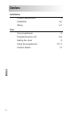
Installation
Installation
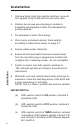
1. Unscrewxingringsfromselectorswitches,moveall
fourtappetstotopofdialandremoveoutercase.
2. Slackentwoscrewssecuringplug-inmoduleto
backplateandseparatemodulefrombackplateby
pullingupwards.
3. Fixbackplatetowall(3holexing).
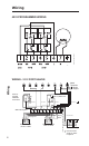
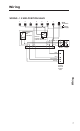
4. Wiremains,motorisedvalve(s),thermostat(s)
accordingtoinstructionsshownonpage6-7.
5. Securecablesunderclampbar.
6. Ensurealldustanddebrishasbeenclearedaway
fromtheareathenpluginprogrammermoduleand
re-tightenthe2retainingscrews-donotovertighten.
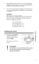
7. Switchonmains,turnbothselectorswitchesto
‘ON’andlightupboileraccordingtomanufacturer’s
instructions.
8. Withbothroomandcylinderthermostatsturnedupto
maximum,checktheswitchingactionofthe4033with
aneonscrewdriverortestlamp.
NOTE:ThisisaClass1productandmustbeearthed.
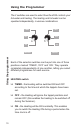
WATER SWITCH
(a) WithselectorswitchinONposition,terminal4
shouldbeLIVE.
(b) WithselectorswitchinOFFposition,terminal5
shouldbeLIVE.
(c) With selector switch in TIMEDposition,terminal
4shouldbeLIVEbetweentappetsA-BandC-D
andterminal5shouldbeLIVEbetweentappets
B-CandD-A.