
Operating instructions
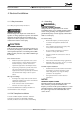
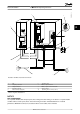

3. Ground the cable in accordance with grounding
instructions provided in 4.3 Grounding.
4. When supplied from an isolated mains source (IT
mains or floating delta) or TT/TN-S mains with a
grounded leg (grounded delta), ensure that
14-50 RFI Filter is set to OFF to avoid damage to
the intermediate circuit and to reduce earth
capacity currents in accordance with IEC 61800-3.
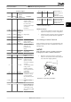
L 1
L 2
L 3
91
92
93
130BT336.10
Illustration 4.9 Connecting to AC Mains
4.8 Control Wiring
•
Isolate control wiring from high power
components in the frequency converter.
•
When the frequency converter is connected to a
thermistor, ensure that the thermistor control
wiring is screened and reinforced/double
insulated. A 24 V DC supply voltage is
recommended.
4.8.1
Control Terminal Types
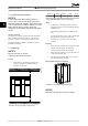
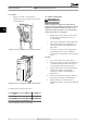
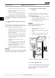
Illustration 4.10 shows the removable frequency converter
connectors. Terminal functions and default settings are
summarised in Table 4.3.
2
3
4
1
130BB921.11
Illustration 4.10 Control Terminal Locations
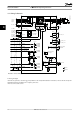
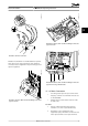
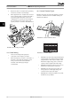
12 13 18 19 27 29 32 33 20 37
39 42 50 53 54 55
61 68 69
130BB931.10
1
2 3
Illustration 4.11 Terminal Numbers
•
Connector 1 provides four programmable digital
inputs terminals, two additional digital terminals
programmable as either input or output, a 24 V
DC terminal supply voltage, and a common for
optional customer supplied 24 V DC voltage.
•
Connector 2 terminals (+)68 and (-)69 are for an
RS-485 serial communications connection
•
Connector 3 provides two analog inputs, one
analog output, 10 V DC supply voltage, and
commons for the inputs and output
•
Connector 4 is a USB port available for use with
the MCT 10 Set-up Software
Electrical Installation
VLT
®
HVAC Drive Operating Instructions
16 MG11AJ02 - Rev. 2013-07-31
44