MAKING MODERN LIVING POSSIBLE Operating Instructions VLT® HVAC Drive FC 102 1.1-90 kW www.danfoss.
VLT® HVAC Drive Operating Instructions Contents Contents 1 Introduction 3 1.1 Purpose of the Manual 3 1.2 Additional Resources 3 1.3 Document and Software Version 3 1.4 Intended Use 3 1.5 Block Diagram of the Frequency Converter 4 1.6 Enclosure Types and Power Ratings 4 1.7 Approvals and Certifications 4 1.8 Disposal Instruction 4 2 Safety 5 2.1 Safety Symbols 5 2.2 Qualified Personnel 5 2.3 Safety Precautions 5 3 Mechanical Installation 7 3.1 Unpacking 7 3.
VLT® HVAC Drive Operating Instructions Contents 5.3 Local Control Panel Operation 21 5.4 Basic Programming 24 5.4.1 Commissioning with SmartStart 24 5.4.2 Commissioning via [Main Menu] 24 5.4.3 Asynchronous Motor Setup 25 5.4.4 Permanent Magnet Motor Setup 25 5.4.5 Automatic Energy Optimization (AEO) 26 5.4.6 Automatic Motor Adaptation (AMA) 26 5.5 Checking Motor Rotation 27 5.6 Local-control Test 27 5.7 System Start-up 27 5.
VLT® HVAC Drive Operating Instructions Introduction 1 1 1 Introduction 1.1 Purpose of the Manual 1.4 Intended Use These operating instructions provide information for safe installation and commissioning of the frequency converter. The frequency converter is an electronic motor controller that The operating instructions are intended for use by qualified personnel.
VLT® HVAC Drive Operating Instructions Introduction 1 1 Area Title 1.5 Block Diagram of the Frequency Converter Illustration 1.1 is a block diagram of the frequency converter's internal components. See Table 1.2 for their functions.
Safety VLT® HVAC Drive Operating Instructions 2 Safety 2 2 WARNING 2.1 Safety Symbols UNINTENDED START! The following symbols are used in this document. WARNING Indicates a potentially hazardous situation which could result in death or serious injury. CAUTION Indicates a potentially hazardous situation which could result in minor or moderate injury. It may also be used to alert against unsafe practices.
2 2 Safety VLT® HVAC Drive Operating Instructions WARNING EQUIPMENT HAZARD! Rotating shafts and electrical equipment can be hazardous. All electrical work must conform to national and local electrical codes. Installation, start-up, and maintenance are performed only by trained and qualified personnel. Failure to follow these guidelines could result in death or serious injury. WARNING WINDMILLING! Unintended rotation of permanent magnet motors causes a risk of personal injury and equipment damage.
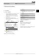
VLT® HVAC Drive Operating Instructions Mechanical Installation 3 Mechanical Installation 3.1 Unpacking 3.1.1 Items Supplied • 1 2 3 4 5 6 Check the packaging and the frequency converter visually for damage caused by inappropriate handling during shipment. File any claim for damage with the carrier. Retain damaged parts for clarification. Make sure the items supplied and the information on the nameplate correspond to the order confirmation. VLT R HVAC Drive www.danfoss.
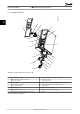
VLT® HVAC Drive Operating Instructions Mechanical Installation 130BB492.10 3.1.3 Product Overview 1 3 3 2 3 4 18 5 17 16 6 15 8 7 8 9 14 10 11 13 12 Illustration 3.
VLT® HVAC Drive Operating Instructions 13 12 11 2 10 DC- 130BB493.10 Mechanical Installation DC+ 1 3 3 06 05 04 03 02 01 9 8 61 68 39 42 Remove jumper to activate 50 53 54 Safe Stop Max. 24 Volt ! 12 3 13 18 19 27 29 32 33 20 7 4 6 5 17 18 FAN MOUNTING QDF-30 19 16 15 14 Illustration 3.
3.2 Installation Environments NOTICE In environments with airborne liquids, particles, or corrosive gases, ensure that the IP/Type rating of the equipment matches the installation environment. Failure to meet requirements for ambient conditions can reduce lifetime of the frequency converter. Ensure that requirements for air humidity, temperature and altitude are met.
Electrical Installation VLT® HVAC Drive Operating Instructions 4 Electrical Installation 4.3 Grounding 4.1 Safety Instructions WARNING See 2 Safety for general safety instructions. LEAKAGE CURRENT HAZARD! WARNING INDUCED VOLTAGE! Induced voltage from output motor cables that run together can charge equipment capacitors even with the equipment turned off and locked out. Failure to run output motor cables separately or use screened cables could result in death or serious injury.
VLT® HVAC Drive Operating Instructions Electrical Installation 3-phase power input DC bus 4 4 +10 V DC Switch Mode Power Supply 10 V DC 24 V DC 15 mA 130/200 mA 88 (-) 89 (+) 50 (+10 V OUT) + - + ON 53 (A IN) S202 ON 54 (A IN) - relay1 ON=0/4-20 mA OFF=0/-10 V DC +10 V DC 03 relay2 01 06 13 (+24 V OUT) 24 V (NPN) 0 V (PNP) 04 19 (D IN) 24 V (NPN) 0 V (PNP) (COM A OUT) 39 (D IN/OUT) 24 V (NPN) 0 V (PNP) 24 V S801 ON 24 V 1 2 (D IN/OUT) 400 V AC, 2 A Analog Output 0/4-20 mA
VLT® HVAC Drive Operating Instructions 130BD529.10 Electrical Installation 2 6 4 4 1 3 4 5 9 10 L1 L2 L3 PE U V W PE 8 7 Illustration 4.2 EMC-correct Electrical Connection 1 PLC 6 Shielded cable 2 Frequency converter 7 Motor, 3-phase and PE 3 Output contactor 8 Mains, 3-phase and reinforced PE 4 Grounding rail (PE) 9 Control wiring 5 Cable insulation (stripped) 10 Equalising min. 16 mm2 (0.025 in) Table 4.1 Legend to Illustration 4.
VLT® HVAC Drive Operating Instructions Electrical Installation 4.5 Access Remove cover with a screw driver (See Illustration 4.3) or by loosening attaching screws (See Illustration 4.4). 4 4 4.6 Motor Connection WARNING INDUCED VOLTAGE! 130BT248.10 • Induced voltage from output motor cables that run together can charge equipment capacitors even with the equipment turned off and locked out. Failure to run output motor cables separately or use screened cables could result in death or serious injury.
U V 96 97 130BD531.10 130BD513.10 VLT® HVAC Drive Operating Instructions Electrical Installation W 98 U V 96 W 97 98 4 4 Illustration 4.5 Motor Connection 88 DC91 L1 95 I N S 96 U 97 V 89 DC+ 81 R- 8 R+ 98 W 99 RELAY 1 A RELAY 2 M 93 L3 130BD577.10 Illustration 4.6, Illustration 4.7 and Illustration 4.8 represent mains input, motor, and grounding for basic frequency converters. Actual configurations vary with unit types and optional equipment.
Electrical Installation VLT® HVAC Drive Operating Instructions Ground the cable in accordance with grounding instructions provided in 4.3 Grounding. 4.8.1 Control Terminal Types 4. When supplied from an isolated mains source (IT mains or floating delta) or TT/TN-S mains with a grounded leg (grounded delta), ensure that 14-50 RFI Filter is set to OFF to avoid damage to the intermediate circuit and to reduce earth capacity currents in accordance with IEC 61800-3. Illustration 4.
VLT® HVAC Drive Operating Instructions Electrical Installation Terminal description Terminal Parameter Default Setting - +24 V DC 18 5-10 [8] Start 19 5-11 [0] No operation 32 5-14 [0] No operation 33 5-15 [0] No operation 27 5-12 [2] Coast inverse 29 5-13 [14] JOG 20 - 37 - 39 - 42 6-50 24 V DC supply voltage. Maximum output current is 200 mA total for all 24 V loads. Usable for digital inputs and external transducers. Digital inputs.
VLT® HVAC Drive Operating Instructions Insert the bared control wire into the contact. 3. Remove the screw driver to fasten the control wire into the contact. 4. Ensure the contact is firmly established and not loose. Loose control wiring can be the source of equipment faults or less than optimal operation. See 8.5 Cable Specifications for control terminal wiring sizes and 6 Application Set-up Examples for typical control wiring connections. 4.8.
Electrical Installation VLT® HVAC Drive Operating Instructions 4.8.6 RS-485 Serial Communication Up to 32 nodes can be connected as a bus, or via drop cables from a common trunk line to 1 network segment. Repeaters can divide network segments. Each repeater functions as a node within the segment in which it is installed. Each node connected within a given network must have a unique node address, across all segments. • Connect RS-485 serial communication wiring to terminals (+)68 and (-)69.
VLT® HVAC Drive Operating Instructions Electrical Installation 4.9 Installation Check List Before completing installation of the unit, inspect the entire installation as detailed in Table 4.5. Check and mark the items when completed. Inspect for ☑ Description Auxiliary equipment • Look for auxiliary equipment, switches, disconnects, or input fuses/circuit breakers that may reside on the input power side of the frequency converter or output side to the motor.
Commissioning VLT® HVAC Drive Operating Instructions 5 Commissioning 1. Confirm that the input voltage is balanced within 3%. If not, correct input voltage imbalance before proceeding. Repeat this procedure after the voltage correction. 2. Ensure that optional equipment wiring, if present, matches the installation application. 3. Ensure that all operator devices are in the OFF position. Panel doors must be closed or cover mounted. 4. Apply power to the unit.
VLT® HVAC Drive Operating Instructions Commissioning 5.3.2 LCP Layout B. Display Menu Keys Menu keys are used for menu access for parameter set-up, toggling through status display modes during normal operation, and viewing fault log data. The LCP is divided into 4 functional groups (see Illustration 5.1). A. Display area B. Display menu keys Key Function 6 Status Shows operational information.
VLT® HVAC Drive Operating Instructions Commissioning D. Operation Keys and Reset Operation keys are located at the bottom of the LCP. 18 Key Function Hand On Starts the frequency converter in local control. • An external stop signal by control input or serial communication overrides the local hand on 19 Off Stops the motor but does not remove power to the frequency converter. 20 Auto On Puts the system in remote operational mode.
VLT® HVAC Drive Operating Instructions 5.4.2 Commissioning via [Main Menu] 1. Press [Main Menu] twice to access parameters. 2. Scroll to 14-22 Operation Mode and press [OK]. 3. Scroll to Initialisation and press [OK]. 4. Remove power to the unit and wait for the display to turn off. 5. Apply power to the unit. Default parameter settings are restored during start-up. This may take slightly longer than normal. Recommended parameter settings are intended for startup and checkout purposes.
Commissioning VLT® HVAC Drive Operating Instructions 7. Use the navigation keys to scroll to 0-01 Language. 8. Select language and press [OK]. 9. If a jumper wire is in place between control terminals 12 and 27, leave 5-12 Terminal 27 Digital Input at factory default. Otherwise, No Operation should be selected in 5-12 Terminal 27 Digital Input. For frequency converters with an optional bypass, no jumper wire is required between control terminals 12 and 27. 10. 3-02 Minimum Reference 11.
5 5 VLT® HVAC Drive Operating Instructions Commissioning Start the motor at nominal speed. If the application does not run well, check the VVCplus PM settings. Recommendations in different applications can be seen in Table 5.6. NOTICE AMA is not relevant for permanent magnet motors. Application Settings Low inertia applications ILoad/IMotor <5 1-17 Voltage filter time const. to be increased by factor 5 to 10 1-14 Damping Gain should be reduced 1-66 Min.
Commissioning VLT® HVAC Drive Operating Instructions 4. 5.5 Checking Motor Rotation In the event of acceleration or deceleration problems, see 7.4 Troubleshooting. See 7.3 List of Warnings and Alarms for resetting the frequency converter after a trip. WARNING MOTOR START! Ensure that the motor, system, and any attached equipment are ready for start. It is the responsibility of the user to ensure safe operation under any condition.
6 Application Set-up Examples The examples in this section are intended as a quick reference for common applications.
VLT® HVAC Drive Operating Instructions 6.1.2 Start/Stop FC +24 V 12 +24 V 13 D IN 18 D IN 19 COM 20 D IN 27 D IN 29 D IN 32 D IN 33 D IN 37 +10 V A IN 50 A IN 54 COM 55 A OUT 42 COM 39 53 130BB804.10 Parameters Function Setting Parameters 5-10 Terminal 18 [8] Start* Digital Input FC +24 V 12 +24 V 13 D IN 18 D IN 19 COM 20 D IN 27 D IN 29 * = Default Value D IN 32 Notes/comments: D IN 37 is an option.
Parameters Setting FC +24 V 12 5-10 Terminal 18 [9] Latched Start Digital Input +24 V 13 D IN 18 5-12 Terminal 27 [6] Stop Inverse Digital Input D IN 19 COM 20 * = Default Value D IN 27 D IN 29 D IN 32 D IN 33 D IN 37 +10 V A IN 50 54 A IN 54 COM 55 COM 55 A OUT 42 A OUT 42 COM 39 +24 V 12 +24 V 13 D IN 18 D IN 19 COM 20 D IN 27 D IN 29 D IN 32 D IN 33 D IN 37 +10 V 50 A IN 53 A IN COM Notes/comments: If 5-12 Terminal 27 Digital Input is set
VLT® HVAC Drive Operating Instructions Application Set-up Examples 6.1.4 RS-485 6.1.5 Motor Thermistor FC +24 V 12 +24 V 13 D IN 18 D IN Setting 8-30 Protocol FC* 8-31 Address 1* 19 8-32 Baud Rate 9600* COM 20 * = Default Value D IN 27 D IN 29 D IN 32 D IN 33 D IN 37 CAUTION Use only thermistors with reinforced or double insulation to meet PELV insulation requirements. Parameters VLT Notes/comments: Select protocol, address and baud rate in the above mentioned parameters.
VLT® HVAC Drive Operating Instructions Diagnostics and Troubleshoo... 7 Diagnostics and Troubleshooting This chapter describes the status messages, warnings and alarms and basic troubleshooting. Remote The speed reference is given from external signals, serial communication, or internal preset references. 7.1 Status Messages Local The frequency converter uses [Hand On] control or reference values from the LCP. Status 799RPM 1(1) 36.4kW 7.83A 0.000 53.2% 130BB037.
Diagnostics and Troubleshoo... DC Stop VLT® HVAC Drive Operating Instructions The motor is held with a DC current (2-01 DC Motor check In 1-80 Function at Stop, Motor Check was selected. A stop command is active. To ensure that a motor is connected to the frequency converter, a permanent test current is applied to the motor. OVC control Overvoltage control was activated in 2-17 Over- Brake Current) for a specified time (2-02 DC Braking Time).
VLT® HVAC Drive Operating Instructions The energy-saving function is enabled. This means that at present the motor has stopped, but it will restart automatically when required. Speed high Motor speed is above the value set in 4-53 Warning Speed High. Speed low Motor speed is below the value set in 4-52 Warning Speed Low. Standby In Auto On mode, the frequency converter will start the motor with a start signal from a digital input or serial communication.
VLT® HVAC Drive Operating Instructions Diagnostics and Troubleshoo... Warning LED Alarm LED Warning On Off Alarm Off On (Flashing) Trip-Lock On On (Flashing) WARNING 5, DC link voltage high The intermediate circuit voltage (DC) is higher than the high-voltage warning limit. The limit is dependent on the frequency converter voltage rating. The unit is still active. WARNING 6, DC link voltage low The intermediate circuit voltage (DC) is lower than the lowvoltage warning limit.
Diagnostics and Troubleshoo... VLT® HVAC Drive Operating Instructions WARNING/ALARM 10, Motor overload temperature According to the electronic thermal protection (ETR), the motor is too hot. Select whether the frequency converter issues a warning or an alarm when the counter reaches 100% in 1-90 Motor Thermal Protection. The fault occurs when the motor runs with more than 100% overload for too long. Troubleshooting Check for motor overheating.
Diagnostics and Troubleshoo... VLT® HVAC Drive Operating Instructions WARNING/ALARM 17, Control word timeout There is no communication to the frequency converter. The warning is only active when 8-04 Control Word Timeout Function is NOT set to [0] Off. If 8-04 Control Word Timeout Function is set to [5] Stop and Trip, a warning appears and the frequency converter ramps down until it stops then displays an alarm. Troubleshooting Check connections on the serial communication cable.
Diagnostics and Troubleshoo... VLT® HVAC Drive Operating Instructions ALARM 33, Inrush fault Too many power-ups have occurred within a short time period. Let the unit cool to operating temperature. WARNING/ALARM 34, Fieldbus communication fault The fieldbus on the communication option card is not working. WARNING/ALARM 36, Mains failure This warning/alarm is only active if the supply voltage to the frequency converter is lost and 14-10 Mains Failure is NOT set to [0] No Function.
Diagnostics and Troubleshoo... VLT® HVAC Drive Operating Instructions WARNING 48, 1.8 V supply low The 1.8 V DC supply used on the control card is outside of allowable limits. The power supply is measured on the control card. Check for a defective control card. If an option card is present, check for an overvoltage condition.
7 7 Diagnostics and Troubleshoo... VLT® HVAC Drive Operating Instructions ALARM 93, Dry pump A no-flow condition in the system with the frequency converter operating at high speed may indicate a dry pump. 22-26 Dry Pump Function is set for alarm. Troubleshoot the system and reset the frequency converter after the fault has been cleared. ALARM 94, End of curve Feedback is lower than the set point. This may indicate leakage in the system. 22-50 End of Curve Function is set for alarm.
Diagnostics and Troubleshoo... VLT® HVAC Drive Operating Instructions 7.4 Troubleshooting Symptom Possible cause Missing input power Display dark/No function Test See Table 4.5 Solution Check the input power source. Missing or open fuses or circuit See open fuses and tripped circuit breaker breaker tripped in this table for possible causes Follow the recommendations provided. No power to the LCP Replace the faulty LCP or connection cable.
7 7 Diagnostics and Troubleshoo... Symptom Motor speed unstable Motor runs rough VLT® HVAC Drive Operating Instructions Possible cause Possible incorrect parameter settings Possible over-magnetisation Test Check settings in parameter group 1-6* Check for incorrect motor settings in all motor parameters Check motor settings in parameter groups Analog I/O mode. For closed-loop operation, check settings in parameter group 20-0* Feedback. 1-2* Motor Data, 1-3* Adv Motor Data, and 1-5* Load Indep.
VLT® HVAC Drive Operating Instructions Specifications 8 Specifications 8.1 Electrical Data 8.1.1 Mains Supply 3x200-240 V AC Type Designation P1K1 P1K5 P2K2 P3K0 P3K7 Typical Shaft Output [kW] 1.1 1.5 2.2 3.0 3.7 Typical Shaft Output [HP] at 208 V 1.5 2.0 2.9 4.0 4.9 A2 A2 A2 A3 A3 IP55/Type 12 A4/A5 A4/A5 A4/A5 A5 A5 IP66/NEMA 4X A4/A5 A4/A5 A4/A5 A5 A5 Continuous (3x200-240 V) [A] 6.6 7.5 10.6 12.5 16.7 Intermittent (3x200-240 V) [A] 7.3 8.3 11.7 13.8 18.
44 4) B1 B1 IP55/Type 12 IP66/NEMA 4X 26.6 8.7 Intermittent (3x200-240 V) [A] Continuous kVA (208 V AC) [kVA] MG11AJ02 - Rev. 2013-07-31 3) 0.96 0.96 16, 10, 16 (6, 8, 6) 10, 10 (8,8,-) 10, 10 (8,8,-) 310 30.8 28.0 11.1 33.9 30.8 B1 B1 B1 B3 10 7.5 P7K5 0.96 35,-,-(2,-,-) 35, 25, 25 (2, 4, 4) 35,-,-(2,-,-) 447 46.2 42.0 16.6 50.8 46.2 B1 B1 B1 B3 15 11 P11K Table 8.
VLT® HVAC Drive Operating Instructions Specifications 8.1.2 Mains Supply 3x380-480 V AC Type Designation P1K1 P1K5 P2K2 P3K0 P4K0 P5K5 P7K5 Typical Shaft Output [kW] 1.1 1.5 2.2 3.0 4.0 5.5 7.5 Typical Shaft Output [HP] at 460 V 1.5 2.0 2.9 4.0 5.0 7.5 10 A2 A2 A2 A2 A2 A3 A3 IP20/Chassis 6) IP55/Type 12 A4/A5 A4/A5 A4/A5 A4/A5 A4/A5 A5 A5 IP66/NEMA 4X A4/A5 A4/A5 A4/A5 A4/A5 A4/A5 A5 A5 Continuous (3x380-440 V) [A] 3 4.1 5.6 7.
46 B1 B1 IP55/Type 12 IP66/NEMA 4X 21 23.1 16.6 16.7 Intermittent (3x380-439 V) [A] Continuous (3x440-480 V) [A] Intermittent (3x440-480 V) [A] Continuous kVA (400 V AC) [kVA] Continuous kVA (460 V AC) [kVA] 20.9 Continuous (3x440-480 V) [A] Intermittent (3x440-480 V) [A] 4) MG11AJ02 - Rev. 2013-07-31 3) 0.98 0.98 10, 10, - (8, 8, -) 10, 10, 16 (6, 8, 6) 16, 10, - (8, 8, -) 392 27.5 25 31.9 29 21.5 22.2 29.7 27 35.2 32 B1 B1 B1 B3 20 15 P15K 0.98 16/6 0.
VLT® HVAC Drive Operating Instructions Specifications 8.1.3 Mains Supply 3x525-600 V AC P1K1 P1K5 P2K2 P3K0 P3K7 P4K0 P5K5 P7K5 Typical Shaft Output [kW] Type Designation 1.1 1.5 2.2 3.0 3.7 4.0 5.5 7.5 IP20/Chassis A3 A3 A3 A3 A2 A3 A3 A3 IP21/NEMA 1 A3 A3 A3 A3 A2 A3 A3 A3 IP55/Type 12 A5 A5 A5 A5 A5 A5 A5 A5 IP66/NEMA 4X A5 A5 A5 A5 A5 A5 A5 A5 Output current Continuous (3x525-550 V) [A] 2.6 2.9 4.1 5.2 - 6.4 9.5 11.
48 B3 B1 B1 B1 IP20/Chassis IP21/NEMA 1 IP55/Type 12 IP66/NEMA 4X 18 20 18.1 17.9 Continuous (3x525-600 V) [A] Intermittent (3x525-600 V) [A] Continuous kVA (525 V AC) [kVA] Continuous kVA (575 V AC) [kVA] 4) MG11AJ02 - Rev. 2013-07-31 3) 0.98 0.98 35,-,-(2,-,-) 525 36 32.7 33.9 34.3 37 34 40 36 B2 B2 B2 B4 22 P22K 16/6 0.98 0.98 35, -, - (2, -, -) 35, 25, 25 (2, 4, 4) 475 28 25.
VLT® HVAC Drive Operating Instructions Specifications 8.1.4 Mains Supply 3x525-690 V AC Type Designation P1K1 P1K5 P2K2 P3K0 P4K0 P5K5 P7K5 Typical Shaft Output [kW] 1.1 1.5 2.2 3.0 4.0 5.5 7.5 Enclosure IP20 (only) A3 A3 A3 A3 A3 A3 A3 Continuous (3x525-550 V) [A] 2.1 2.7 3.9 4.9 6.1 9.0 11 Intermittent (3x525-550 V) [A] 3.4 4.3 6.2 7.8 9.8 14.4 17.6 Continuous kVA (3x551-690 V) [A] 1.6 2.2 3.2 4.5 5.5 7.5 10 Intermittent kVA (3x551-690 V) [A] 2.6 3.5 5.
8 8 VLT® HVAC Drive Operating Instructions Specifications Type Designation P37K P45K P55K P75K P90K High/Normal Load NO NO NO NO NO Typical Shaft Output at 550 V [kW] 30 37 45 55 75 Typical Shaft Output at 690 V [kW] 37 45 55 75 90 IP20/Chassis B4 C3 C3 D3h D3h IP21/NEMA 1 C2 C2 C2 C2 C2 IP55/NEMA 12 C2 C2 C2 C2 C2 Output current Continuous (3 x 525-550 V) [A] Intermittent (60 s overload) (3 x 525-550 V) [A] 43 54 65 87 105 47.3 59.4 71.5 95.7 115.
Specifications VLT® HVAC Drive Operating Instructions 8.2 Mains Supply Mains supply Supply Terminals Supply voltage Supply voltage Supply voltage L1, L2, L3 200-240 V ±10% 380-480 V/525-600 V ±10% 525-690 V ±10% Mains voltage low/mains drop-out: During low mains voltage or a mains drop-out, the frequency converter continues until the intermediate circuit voltage drops below the minimum stop level, which corresponds typically to 15% below the frequency converter's lowest rated supply voltage.
8 8 Specifications VLT® HVAC Drive Operating Instructions Ambient temperature3) Minimum ambient temperature during full-scale operation Minimum ambient temperature at reduced performance Temperature during storage/transport Maximum altitude above sea level without derating Max.
VLT® HVAC Drive Operating Instructions Specifications 2) Except Safe Torque Off input Terminal 37. See for further information about terminal 37 and Safe Torque Off. 4) When using a contactor with a DC coil inside in combination with Safe Torque Off , it is important to make a return way for the current from the coil when turning it off. This can be done by using a freewheel diode (or, alternatively, a 30 or 50 V MOV for quicker response time) across the coil.
8 8 Specifications VLT® HVAC Drive Operating Instructions 500 Ω Max. error: 0.5% of full scale 12 bit Max. load GND - analog output Accuracy on analog output Resolution on analog output The analog output is galvanically isolated from the supply voltage (PELV) and other high-voltage terminals.
VLT® HVAC Drive Operating Instructions Specifications Control card, 10 V DC output Terminal number Output voltage Max. load 50 10.5 V ±0.5 V 15 mA The 10 V DC supply is galvanically isolated from the supply voltage (PELV) and other high-voltage terminals.
VLT® HVAC Drive Operating Instructions Specifications 8.8 Fuse Specifications It is recommended to use fuses and/or circuit breakers on the supply side as protection in case of component break-down inside the frequency converter (first fault). NOTICE This is mandatory in order to ensure compliance with IEC 60364 for CE or NEC 2009 for UL. The fuses below are suitable for use on a circuit capable of delivering 100,000 Arms (symmetrical), depending on the frequency converter voltage rating.
VLT® HVAC Drive Operating Instructions Specifications 380-480 V Enclosure type Power [kW] Recommended fuse size Recommended Max. fuse size Recommended circuit breaker (Moeller) Max. trip level [A] A2 1.1-4.0 gG-10 (1.1-3) gG-16 (4) gG-25 PKZM0-25 25 A3 5.5-7.
8 8 VLT® HVAC Drive Operating Instructions Specifications 525-690 V Enclosure type Power [kW] Recommended fuse size Recommended Max. fuse size Recommended circuit breaker (Moeller) Max. trip level [A] A3 1.1 1.5 2.2 3 4 5.5 7.
VLT® HVAC Drive Operating Instructions Specifications Recommended max. fuse Power [kW] Ferraz- FerrazShawmut Bussmann Littel fuse Type JFHR22) JFHR2 A2K-10-R FWX-10 A2K-15-R FWX-15 ATM-R-20 A2K-20-R KLN-R-25 ATM-R-25 5012406-032 KLN-R-30 5.5 5014006-050 7.5 5014006-063 11 SIBA Littel fuse Type RK1 1.1 1.5 Type RK1 Shawmut Type CC Type RK13) 5017906-010 KLN-R-10 ATM-R-10 5017906-016 KLN-R-15 ATM-R-15 2.2 5017906-020 KLN-R-20 3.0 5017906-025 3.
8 8 VLT® HVAC Drive Operating Instructions Specifications Recommended max. fuse Power [kW] SIBA Littel fuse Type RK1 Type RK1 FerrazShawmut Type CC FerrazShawmut Type RK1 Bussmann JFHR2 FerrazShawmut J FerrazShawmut JFHR21) Littel fuse JFHR2 1.1 5017906-006 KLS-R-6 ATM-R-6 A6K-6-R FWH-6 HSJ-6 - - 1.5-2.
VLT® HVAC Drive Operating Instructions Specifications 3x525-690 V Recommended max. fuse Power [kW] Bussmann Type RK1 Bussmann Type J Bussmann Type T Bussmann Type CC Bussmann Type CC Bussmann Type CC [kW] 1.1 KTS-R-5 JKS-5 JJS-6 FNQ-R-5 KTK-R-5 LP-CC-5 1.5-2.2 KTS-R-10 JKS-10 JJS-10 FNQ-R-10 KTK-R-10 LP-CC-10 3 KTS-R15 JKS-15 JJS-15 FNQ-R-15 KTK-R-15 LP-CC-15 4 KTS-R20 JKS-20 JJS-20 FNQ-R-20 KTK-R-20 LP-CC-20 5.
62 A a Distance between mounting holes MG11AJ02 - Rev. 2013-07-31 70 Distance between mounting holes 9 f 4.9 ø5.5 e - 6.6 6.5 ø5.5 ø11 8.0 220 205 110 190 170 130 257 374 268 - Click 20 Chassis 7.0 6.5 ø5.5 ø11 8.0 222 207 110 190 170 130 350 - 375 21 Type 1 1.1-7.5 5.5-7.5 3.0-3.7 A3 1.1-7.5 Table 8.22 Power Ratings, Weight and Dimensions Click Plastic cover (low IP) 5.3 9 ø5.5 ø11 8.
Appendix VLT® HVAC Drive Operating Instructions 9 Appendix 9.
64 MG11AJ02 - Rev.
6-63 6-64 8-** 8-0* 8-01 8-02 8-03 8-04 8-05 8-06 8-07 8-08 8-09 8-1* 8-10 8-13 8-3* 8-30 8-31 8-32 8-33 8-34 8-35 8-36 8-37 8-4* 8-40 8-42 8-43 8-5* 8-50 8-52 8-53 8-54 8-55 8-56 8-7* 8-70 8-72 8-73 8-74 8-75 8-8* 8-80 8-81 8-82 8-83 8-84 8-85 8-89 8-9* 8-90 8-91 8-94 8-95 8-96 9-** 9-00 9-07 Terminal X30/8 Output Bus Control Terminal X30/8 Output Timeout Preset Comm.
16-22 16-26 16-27 16-3* 16-30 16-32 16-33 16-34 16-35 16-36 16-37 16-38 16-39 16-40 16-41 16-43 16-49 16-5* 16-50 16-52 16-53 16-54 16-55 16-56 16-58 16-6* 16-60 16-61 16-62 16-63 16-64 16-65 16-66 16-67 16-68 16-69 16-70 16-71 16-72 16-73 16-75 16-76 16-77 16-8* 16-80 16-82 16-84 16-85 16-86 16-9* 16-90 16-91 16-92 16-93 16-94 16-95 16-96 18-** 18-0* Torque [%] Power Filtered [kW] Power Filtered [hp] Drive Status DC Link Voltage Brake Energy /s Brake Energy /2 min Heatsink Temp. Inverter Thermal Inv. Nom.
24-9* 24-90 24-91 24-92 24-93 24-94 24-95 24-96 24-97 24-98 24-99 25-** 25-0* 25-00 25-02 25-04 25-05 25-06 25-2* 25-20 25-21 25-22 25-23 25-24 25-25 25-26 25-27 25-28 25-29 25-30 25-4* 25-40 25-41 25-42 25-43 25-44 25-45 25-46 25-47 25-5* 25-50 25-51 25-52 25-53 25-54 25-55 25-56 25-58 25-59 25-8* 25-80 25-81 25-82 25-83 25-84 25-85 25-86 25-9* 25-90 Multi-Motor Funct.
Index VLT® HVAC Drive Operating Instructions Index Default Settings................................................................................... 23 Digital Input...................................................................... 17, 33, 36, 18 Dimensions............................................................................................ 62 A Abbreviations....................................................................................... 63 Discharge Time...........................
Index VLT® HVAC Drive Operating Instructions Installation Installation................................................................................... 17, 20 Environments.................................................................................... 10 Output Current.......................................................................................... 32, 35 Terminal.............................................................................................. 21 Intended Use.................
Index VLT® HVAC Drive Operating Instructions Sleep Mode............................................................................................ 34 Speed Reference............................................................. 18, 27, 28, 32 Start Up.................................................................................................... 24 Start/stop Command......................................................................... 29 Status Mode.................................................
Index VLT® HVAC Drive Operating Instructions MG11AJ02 - Rev.
www.danfoss.com/drives Danfoss Power Electronics A/S Ulsnaes 1 6300 Graasten Denmark www.danfoss.com 130R0083 MG11AJ02 *MG11AJ02* Rev.