Installation Manual Danfoss GX 850 Dual Zone Automatic Control Panel DanfossGX BRINGING WARMTH TO LIFE
CONTENTS - GX 850 Dual Zone ACP Page Description ..................................................................................................................... 2 Specifications ................................................................................................................ 2 Schematic Diagram...................... ............................................................................... 2 Installation Examples .....................................................................
Danfoss GX 850 Dual Zone Automatic Control Panel (ACP) The GX 850 Dual Zone Automatic Control Panel (ACP) is the most optimal solution for keeping an area free of ice and snow. The GX 850 ACP is like having a mini weather station monitoring your installation 24 hours a day. Collecting temperature and relative humidity information from sensors embedded in the surface material, it is able to accurately sense when to turn the system on and off.
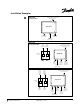
Installation Examples Heater power supply (600V max.). Direct connect to internal contactor. SINGLE ZONE (less than 50amps) GX 850 ACP 120V control power input Zone A Heaters (50A max) Ground or gutter sensors SINGLE ZONE (greater than 50amps) Heater Heater power power supply supply 600V max. 600V max. Contactor Panel A Contactor Panel GX 850 ACP B Heaters Heaters DUAL ZONE Heater power supply (600V max.). Direct connect to internal contactor.
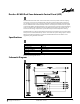
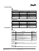
17 18 White 3 N 5 N 120V Output to Zone B 120V Output to Zone A White 15 16 Red White 18 Ground or Gutter Sensors Zone B Ground 120V Control power input White 15 16 17 Red G Ground or Gutter Sensors Zone A N Black L1 Black Terminal Block The required power output for your heating system should be determined by a qualified electrician.
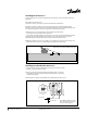
Installing Ground Sensors Correct placing of the sensor(s) is important for the system to work as intended. Some basic guidelines: The number of ground sensors: 1) The more sensors you add to your system the better the performance. 2) The basic principle is to place one sensor where the snow/ice will appear first (for fast detection) and one sensor where the snow/ice will disappear last (for complete melting). If it is not obvious just place the sensors as far apart from each other as possible.
Installing a Sensor Cable A feeder cable for a sensor may be needed. A 50’ (15m) cable is supplied with each sensor. Approx. 1.5’ (0.5m) of this cable should be coiled inside the bottom of the sensor tube. The remaining cable may be extended. The feeder cable must be a four wire cable. Installing a Ground Sensor and a Conduit The sensor and the conduit may be installed in connection with the actual construction work and connected at a later date.
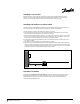
Installing Roof Sensors Correct placing of the sensor(s) is important for the system to work as intended. The number of roof sensors: 1) The more sensors you add to your system the better the performance. 2) The basic principle is to place one sensor where the snow/ice will appear first (for fast detection) and one sensor where the snow/ice will disappear last (for complete melting). If it is not obvious just place the sensors as far apart from each other as possible.
Factory Settings Ground Application Settings Function Moisture level Factory settings 50 Standby temperature Melting temperature Post-heat Clogged drain System mode 27°F (-3°C) 39°F (4°C) 1 hour On Automatic Options 5 to 95 (5 being the most sensitive to moisture) - 4°F to 32°F (-20°C to 0°C) 34°F to 50°F (1°C to 10°C) 0 to 9 hours On/off Automatic Constant On (manual timer, 9H) Manually Off Roof Application Settings Function Moisture level Factory settings 50 Melting temperature Post-heat Clogged dr
Presetting CD-ST 2 CD-ST 2 Presetting Copyright 2009 Danfoss Inc. VD.33.U1.02 © Danfoss 06/99 EFH.IM.
DANFOSS GX 850 DUAL ZONE ACP WARRANTY For a period of two (2) years from the date of purchase Danfoss warrants that the Danfoss GX 850 Dual Zone Automatic Control Panel (ACP) is free from defects in material, design and workmanship. The warranty is only valid if the warranty certificate is correctly filled out and the installation is in accordance with the installation instructions. The warranty certificate shall be presented to Danfoss in the case a claim is made.
Danfoss can accept no responsibility for possible errors in catalogues, brochures, other printed materials, and website information. Danfoss reserves the right to alter its products without notice. This also applies to products already on order provided that such alteration can be made without subsequent changes being necessary in specifications already agreed upon. All trademarks in this material are property of the respective companies.