ERC 113 refrigeration controller Bottle cooler controller ERC 113 This reference manual is intended to be used primarily by OEMs for the purposes of programming ERC 113. It may also be useful for technicians. It is not intended as a user guide for end users. www.danfoss.
User manual ERC 113 refrigeration controller Introduction ERC 113 The ERC 113 is an electronic stand-alone controller designed to optimise total cost savings. Particularly suited for OEM customers, the controller easily meets requirements for a time-saving and flexible production setup. Programming can be carried out in just 10 seconds using the unique Danfoss docking station. Moreover, the ERC 113 is easy to mount and comes with just one code number to facilitate inventory management.
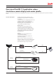
User manual ERC 113 refrigeration controller Overview of the ERC 113 application setups: stand-alone, remote display and remote spindle. The ERC 113 stand-alone controller can be equipped with a variety of accessories, including remote display, remote spindle and multiple sensors. Overview of the system The ERC 113 stand-alone controller is easily programmed using the Danfoss docking station or a gateway.
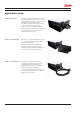
User manual ERC 113 refrigeration controller Application setup 1) ERC 113 stand-alone The ERC 113 is an IP-rated stand-alone controller for use in applications such as beer coolers and counter-top bottle coolers (e.g. in petrol stations). With input from multiple sensors, the cost-efficient controller delivers energy-saving routines as well as providing control of compressor, light, fan and defrost functions.
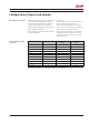
User manual ERC 113 refrigeration controller Configuration of inputs and outputs ERC 113 inputs and outputs Possible input and output connections The ERC 113 inputs and outputs are configurable by the customer. Before getting started it is a good idea to check if all inputs are configured correctly and match the sensors attached. For instance: Danfoss supplies only 2-pole defrost sensors, so input "S3" will most likely be used as a defrost/evaporator temperature sensor input.
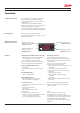
User manual ERC 113 refrigeration controller Operation Software tool/Gateway The controller can be controlled in three ways: Using "Software tool", the Danfoss Docking Station or manually by means of the buttons on the front panel. "Software tool" is licenced Danfoss software offering easy parameter set up via a USB gateway. This software is supplied separately; for technical literature and further information, please contact your local Danfoss representative.
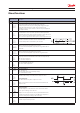
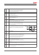
User manual ERC 113 refrigeration controller Menu/functions ERC menu code "tHE Description Thermostat settings "SEt" Min. -100.0°C Max. 200.0°C Default 2.0°C "SPr" Min. 0.0 Max. 1.0 Default 0.5 "diF" Min. 0.0 K Max. 20.0 K Default 2.0 K "HSE" Min. -100.0°C Max. 200.0°C Default 50.0°C "LSE" Min. -100.0°C Max. 200°C Default -35.0°C "iCi" Min. no Max. yes Default no "SSA" Min. 0 Max. 80 Default 30 FAn Set point This parameter defines the desired temperature (set point).
User manual "FdC" Min. -10.0 K Max. 10.0 K Default 0.0 K "Fdt" Min. 0 s Max. 999 s Default 0 s Lig ERC 113 refrigeration controller Fan Δt cut in Delta T for fan to cut in which the temperature offset comparing with thermostat cut in temperature. Fan stop time on door open The delay with wich the fan will be stopped after the door has been opened. "0": fan stop immediately when door open. "1-998": delay for fan stop after door open. "999": fan keep running all the time during door open.
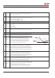
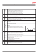
User manual "Prt" Min. 0.0 K Max. 10.0 K Default 0.1 K dEF ERC 113 refrigeration controller Pull Down Reduction Temperature Δt The controller calculates a lower set point during pull down mode to increase the cooling capacity of your appliance. For each hour the cabinet temperature is above the pull down initiate temperature, the set point is reduced with the value of "Prt". Defrost settings "dFt" Default no "Add" Min. no Max. yes Default no "dtt" Min. 0.0°C Max. 25.0°C Default 6.0°C "drt" Min. 0.
User manual "Ftd" Min. -25.0°C Max. 25.0°C Default 25.0°C "dFA" Min. no Max. yes Default no "dCt" Min. no Max. yes Default no "doC" Min. 0 hour Max. 24 hour Default 0 hour "dEt" Min. -50.0°C Max. 0.0°C Default -50.0°C "ddt" Min. 0.0 K Max. 30.0 K Default 5.0 K "idi" Min. 0 hour Max. 96 hour Default 3 hour "idd" Min. 0 Max. 999 Default 100 CoP Fan Start Temperature This only applies if an evaporator temperature sensor is fitted.
User manual "uLi" Min. 0 V a.c. Max. 270 V a.c. Default 0 V "uLo" Min. 0 V a.c. Max. 270 V a.c. Default 0 V "uHi" Min. 0 V a.c. Max. 270 V a.c. Default 270 V "EHd" Default no "Ert" Min. 0 min Max. 60 min Default 0 min "ESt" Min. 0 min Max. 60 min Default 1 min "CSt" Min. 0 min Max. 30 min Default 2 min "Crt" Min. 0 min Max. 30 min Default 0 min "Cot" Min. 0 min Max. 480 min Default 0 min "Cdd" Min. 0 min Max. 15 min Default 0 min "Srt" Min. 0 min Max.
User manual "Pod" Min. 0 s Max. 300 s Default 300 s "Pot" Min. -100.0°C Max. 200.0°C Default -100.0°C Con ERC 113 refrigeration controller Power ON Delay This is the delay in seconds between power-on and the compressor being activated. Depends on the power ON temperature setting as explained below.
User manual "rES" Min. 0.1 Max. 1 Default 0.1 "rLt" Min. no Max. yes Default no "ddL" Min. 0 s Max. 10 min Default 0 min "doF" Min. -10.0 K Max. 10.0 K Default 0.0 K "dLt" Min. 0 min Max. 60 min Default 15 min "SEC" Min. no Max. yes Default no "SSC" Min. no Max. yes Default no "SHo" Min. no Max. yes Default no "SdF" Min. no Max. yes Default yes "SCS" Min. no Max. yes Default yes "SFS" Min. no Max.
User manual "SdS" Min. no Max. yes Default yes "SES" Min. no Max. yes Default yes ALA Show Defrost symbol "no": defrost symbol will not show on display. "yES": show defrost symbol on display. Show ECO symbol "no": ECO symbol will not show on display. "yES": show ECO symbol on display. Alarm settings "HAt" Min. -100.0°C Max. 200°C Default 15.0°C "LAt" Min. -100.0°C Max. 200°C Default -50.0°C "Htd" Min. 0 min Max. 240 min Default 30 min "Ltd" Min. 0 min Max. 240 min Default 0 min "Pdd" Min.
User manual "ACA" Min. no Max. yes Default yes AHC ERC 113 refrigeration controller Auto Clear of Alarm/Error/ACA If this parameter is set to "nO": The alarm status will not disappear automatically even if the condition which caused the alarm is no longer valid or present. If set to "yES": As soon as the condition which caused the alarm is no longer valid or present, the alarm status will automatically change back to inactive. There will be no trace of the alarm having occurred.
User manual "ECt" Min. 0 min Max. 180 min Default 30 min "Edd" Min. 0 min Max. 180 min Default 180 min "EPd" Min. 0 min Max. 180 min Default 120 min "SLd" Min. 0 Max. 80 Default 5 "SLn" Min. 0 Max. 80 Default 3 "tto" Min. 0 hour Max. 168 hour Default 0 hour "LSd" Min. 0 min Max. 180 min Default 0 min "Euu" Min. no Max. yes Default yes "CLH" Min. 0 hour Max. 24 hour Default 6 hour "ErL" Min. 0 min Max. 240 min Default 120 min "HoL" Min. 0 hour Max.
User manual "diE" Min. 0.0 K Max. 10.0 K Default 2.0 K "FoE" Min. 0 s Max. 960 s Default 0 s "FSE" Min. 0 s Max. 960 s Default 0 s "ELC" Default on "ELd" Min. 0 min Max. 10 min Default 5 min ASi ERC 113 refrigeration controller ECO Differential Thermostat differential for ECO. ECO Fan on cycle On time for fan during compressor OFF period in ECO mode. ECO Fan stop cycle OFF time for fan during compressor OFF period in ECO mode.
User manual "S1C" Default Stn "S2C" Default Stn "S3C" Default Stn "S4C" Default Stn "S5C" ERC 113 refrigeration controller S1 Config/S1C S2 Config/S2C S3 Config/S3C S4 Config/S4C S5 Config/S5C (remote display) S6 Config/S6C (remote display) Available options are: "Stn": for a standard temperature sensor NTC 5 K @ 25°C and TPE precision. "Htn": for a high temperature sensor NTC 100 K @ 25°C. "Pt1": for a temperature sensor Pt1000 ohm @ 0°C (only "S4").
User manual "o2C" Default dEF "o3C" Default FAn "o4C" Default Lig ERC 113 refrigeration controller D02 Config/o2C D03 Config/o3C D04 Config/o4C D05 Config/o5C "no": not used. "dEF": electric defrost heater/valve for hot gas. "ALA": alamr output. "FAn": fan control. "Lig": light control.
User manual Ser ERC 113 refrigeration controller Service information settings The parameters in the following section are READ ONLY and cannot be changed by the user. They provide information for technicians and OEM users. NOTE: the only parameters that can be configured are: "oEL", "oEn", "oEH". These parameters allow OEMs to enter their own product code. 20 "ACt" Accumulated Comp.
User manual ERC 113 refrigeration controller "oEn" OEM code Middle "oEH" OEM code High "PAr" Parameter version OEM parameter version number [requires EKA copy key update]. "CHd" Manufacturing date Programme date WWY: week number and year number (2010-19). "SFC" Set as Default Resets all parameters to last good OEM settings. "Ctt" Condenser Temp Temperature of the condensor sensor. "Et1" Evaporator1 Temp Temperature of the evaporator sensor1.
User manual ERC 113 refrigeration controller Troubleshooting Problem Probable cause Remedy Compressor does not start Waiting for compressor delay timer Defrost in progress Line voltage to compressor too low or too high Check CoP->CSt Check CoP ->Pot /Pod Check dEF ->dit, dot Check CoP->uLi, uLo, uHi Fan does not start Door is open or door contact is defective Fan stops when door is opened Check that door contact is ok Defrost does not start Controller in pull down mode Defrost might be delayed
User manual ERC 113 refrigeration controller Technical specs Power Supply Rated Power Input Output 100 - 240 VAC (±10%), switch mode power supply Average 0.7 W 5 Inputs: 4 Analogue & Digital, 1 Digital; user specific assignment • Door sensor: • Air/Evaporator/Condenser all types, user specific • Light sensor: • DP: for remote Danfoss ECO light sensor communication UL60730 120 V a.c.: 16 A resistive/FLA16/LRA72 "DO1" (Compressor relay) 240 V a.c.
User manual ERC 113 refrigeration controller Dimensions ERC 113 35 90.6 29 91.5 30 81 di S3 S2 S1 6 5 4 3 2 1 105 Remote spindle 17.4 3.93 15.7 35 Ø5.90 Ø1.5 Remote display ^ ^ 28 mm 36,5 mm 47,25 mm 51,25 mm 78,25 mm 71 mm 71 mm 30 mm 28,5 mm Front mounting (Lock with frame) 24 DKRCC.ES.RL0.F5.
User manual ERC 113 refrigeration controller Code numbers Type Code no. I-Pack ERC 113 stand alone Type Code no.
User manual ERC 113 refrigeration controller Typical applications No-frost freezer/sub-zero cooler N 2 3 1 DO1 Fan Compressor Defrost Heater L 4 5 DO2 AI/DI’s Lights 100 – 240VAC SMPS DO3 S1 6 ERC 113D Controller DO’s DO4 S2 S3 S4 ERC 113D di 080G3253 Door Switch Controller Temperature Sensor for Cabinet Temperature Control Temperature Sensor for Evaporator Temperature Control PVC Standard Connector type (S1) 3-pole PVC Standard Connector type (S2) 2-pole 470 mm 1000 mm 150
User manual ERC 113 refrigeration controller No-frost freezer/sub-zero cooler 100 – 240VAC SMPS N 2 3 1 DO1 Fan Compressor Defrost Heater L 4 DO2 AI/DI’s 5 DO’s ERC 113C Controller S3 S4 DO3 S1 S2 di ERC 113C 080G3252 Controller LL Temperature Sensor for Cabinet Temperature Control PVC Standard Connector type (S1) 3-pole Temperature Sensor for Evaporator Temperature Control Ambient Light PVC Standard Connector type (S2) 2-pole Door input Light sensor Connector type (S3) 3-pole
User manual ERC 113 refrigeration controller Sensor placement Control sensor The control sensor must always be connected and is used for controlling the cut-in and cut-out of the compressor according to the set point. The sensor is also used for the displayed temperature. Control sensor Vertical coolers with fan Most common placement is in the return air to the evaporator.
User manual ERC 113 refrigeration controller Condenser sensor The condenser sensor is used to protect the compressor against high pressure when the condenser is blocked or the condenser fan fails. Placement of sensor Place the sensor at the liquid side of the condenser. Use a metal bracket or metal tape to ensure good thermal conductivity. Be sure that the cable does not pass hot spots at the compressor or condenser that exceeds 80°C.
User manual ERC 113 refrigeration controller Application matrix Stand-alone Output Application ERC type DO1 DO2 Input DO3 DO4 S1 (C1) S2 (C2) S3 (C3) Di (C4) Control Defrost Condenser or ambient light Door Standard beverage cooler ERC 113C Comp Fan Lamp Sub-zero beverage cooler ERC 113D Comp Heater Fan Lamp Control Defrost Condenser or ambient light Door Out-door beverage cooler ERC 113D Comp Heater Fan Lamp Control Condenser Ambient light Door No frost freezer w.
User manual ERC 113 refrigeration controller Produced by Danfoss A/S (ADAP-KOOL®) | 2016-07 DKRCC.ES.RL0.F5.
User manual ERC 113 refrigeration controller Danfoss can accept no responsibility for possible errors in catalogues, brochures and other printed material. Danfoss reserves the right to alter its products without notice. This also applies to products already on order provided that such alternations can be made without subsequential changes being necessary in specifications already agreed. All trademarks in this material are property of the respective companies.