
Submittal Sheet


Data sheet Thermostatic expansion valves, type TUA/TUAE and TCAE
7DKRCC.PD.AG0.A4.22 / 520H8945
Determine required valve capacity.
Use the design evaporator capacity, Q
e
, to select
the required valve size at a given evaporating
temperature. If necessary, correct the evaporator
capacity for subcooling and pressure drop in
liquid line (pdw).
Subcooled liquid refrigerant entering the
evaporator increases evaporator capacity, so that
a smaller valve may be required.
In this example, the subcooling is: Δ
tsub
= t
c
− tl =
75 − 55 = 20°F
From the subcooling correction factor table, see
below, we nd the appropriate correction factor
“f
sub
” equals 1.06 for Δt
sub
= 20°F.
From the Distributer correction factor table, see
below, we nd the appropriate correction factor
“fp” equals 0.92 for pressure drop liquid = 25 psig
and t
evap
= +10°F
For optimum performance, it is important
to select a TU/TC valve according to system
conditions and application. Selecting an incorrect
valve will result in operational diculties or poor
system performance.
The following procedure will help you select the
correct valve for your needs.
Example:
Refrigerant = R407C
Evaporator capacity:
Qe = 30,000 Btu (2.5 TR)
Evaporating temperature: te = +10°F
Condensing temperature: tc = +75°F
Liquid refrigerant temperature: tl = +55°F
Pressure drop in Evaporator: dp
evap
: 3 psi
Presure drop in Condenser: dp
cond
: 3 psi
Pressure drop in distributer: 15 psi
Pressure drop in other components in liquid line:
dp line components: 2 psi
Determine the pressure drop in the liquid line.
Pressure drop in liquid line (dp
liquid
) = the
sum of other pressure drops in the liquid line,
evaporator, and distributor.
In this example, the total pressure drop in the
liquid line will be:
dp
liquid
= dp
evap
+ dp
cond
+ dp
distrib
+ dp
linecomp
dp
liquid
: 3 + 3 + 15 +2 = 23 psi
Now, determine the required valve capacity
by multiplying the evaporator capacity by the
correction factor for subcooling and pressure
drop
Required valve capacity
Qe × F
sub
x fp = 2.5 × 1.06 x 0.92 = 2.56 TR
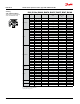
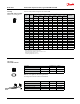
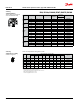
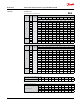
Use the calculated valve capacity to select the
corresponding orice size from the capacity table
for R407C as indicated below.
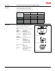
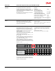
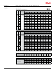
Subcooling [°F] 2 7 10 20 30 40 50 60 70 80 90
Correction factor 0.95 0.98 1.00 1.06 1.12 1.19 1.25 1.31 1.37 1.43 1.49
Evaporating temperature [°F] -40 -30 -20 -10 0 10 20 30 40 50
"Pressure drop [psi]"
0 1 1 1 1 1 1 1 1 1 1
15 0.96 0.96 0.96 0.96 0.96 0.95 0.95 0.95 0.94 0.93
25 0.93 0.93 0.93 0.93 0.93 0.92 0.92 0.91 0.90 0.88
30 0.92 0.92 0.92 0.91 0.91 0.90 0.90 0.89 0.88 0.86
*calculated at 90°F condensing temperature
Subcooling correction factor 'fsub' ∆t
sub
Distributer correction factor 'fp' *
Step 2
Step 1
Selection