
Technical Bulletin
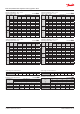


Capacity in kW. Range: -40 – 10 °C.
Opening superheat sh = 4 K
SI units R407C
Valve
type
Orice
no.
Cond.
temp.
[°C]
Evap. temp. [°C]
-40 -30 -20 -10 0 10
TE 5
0.5 25
4.62 5.82 7.18 8.56 9.66 10.0
01 25 8.48 10.7 13.2 15.7 17.7 18.2
02 25 11.9 15.0 18.4 21.8 24.4 24.9
03 25 15.0 19.0 23.6 28.1 31.6 32.4
04 25 20.1 25.6 31.9 38.2 42.9 43.7
TE 12
05 25 20.9 27.9 36.2 45.1 52.7 55.9
06 25
26.6 35.8 46.9 59.1 69.8 74.5
07 25 34.5 46.5 61.4 78.2 93.2 99.8
TE 20
08 25
49.3 63.2 79.4 96.4 110 114
09 25 54.3 70.6 90.4 112 131 138
TE 55
10 25
63.6 82.2 105 130 153 166
11 25 70.1 90.5 115 143 168 181
12 25 75.5 97.8 125 156 186 202
13 25 92.1 120 154 192 228 246
Subcooling correction factor, f
sub
Subcooling [K] 2 4 10 15 20 25 30
Correction factor 0.98 1.00 1.07 1.12 1.18 1.23 1.28
Distributer correction factor, f
p
SI units R407C
Pressure drop
[bar]
∆p
Evap. temp. [°C]
-40 -30 -20 -10 0 10
Correction factor
0 1 1 1 1 1 1
1 0.96 0.96 0.96 0.95 0.95 0.93
1.5 0.94 0.94 0.94 0.93 0.92 0.90
2 0.92 0.92 0.91 0.91 0.89 0.86
Calculated at 32 °C condensing temperature.
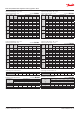
Distributer correction factor, f
p
US units R407C
Pressure drop
[psi]
∆p
Evap. temp. [°F]
-40 -20 0 20 40 50
Correction factor
0 1 1 1 1 1 1
15 0.96 0.96 0.96 0.95 0.94 0.93
25 0.93 0.93 0.93 0.92 0.90 0.88
30 0.92 0.92 0.91 0.90 0.88 0.86
Calculated at 90 °F condensing temperature.
Capacity in kW. Range: -40 – 10 °C.
Opening superheat sh = 4 K
SI units R407C
Valve
type
Orice
no.
Cond.
temp.
[°C]
Evap. temp. [°C]
-40 -30 -20 -10 0 10
TE 5
0.5 35
4.54 5.77 7.22 8.82 10.4 11.5
01 35
8.34 10.6 13.3 16.2 19.0 20.9
02 35
11.7 14.9 18.6 22.7 26.4 28.7
03 35 14.7 18.7 23.5 28.8 33.8 37.0
04 35 19.4 25.0 31.7 39.1 46.0 50.2
TE 12
05 35 20.2 26.7 34.7 44.2 54.0 61.6
06 35 25.4 33.9 44.7 57.6 71.3 82.1
07 35 32.2 42.6 56.3 73.2 91.7 107
TE 20
08 35 47.0 60.3 76.7 95.6 114 127
09 35 50.5 65.4 84.4 108 132 151
TE 55
10 35 58.3 76.3 98.9 126 155 180
11 35 63.9 83.5 108 138 169 196
12 35
68.2 89.4 116 149 185 216
13 35 81.8 108 141 181 225 262
Capacity in TR. Range: -40 – 50 °F.
Opening superheat sh = 7.2 °F.
US units R407C
Valve
type
Orice
no.
Cond.
temp.
[°F]
Evap. temp. [°F]
-40 -20 0 20 40 50
TE 5
0.5 95 1.29 1.68 2.15 2.66 3.10 3.25
01 95 2.37 3.09 3.95 4.88 5.68 5.93
02 95
3.32 4.34 5.54 6.81 7.85 8.15
03 95
4.16 5.45 7.00 8.67 10.1 10.5
04 95 5.52 7.30 9.46 11.8 13.7 14.3
TE 12
05 95 5.74 7.80 10.4 13.5 16.4 17.5
06 95 7.21 9.92 13.5 17.7 21.8 23.3
07 95 9.15 12.5 17.0 22.5 28.2 30.3
TE 20
08 95 13.4 17.6 22.9 29.0 34.4 36.1
09 95 14.4 19.1 25.4 32.9 40.2 42.9
TE 55
10 95
16.6 22.3 29.7 38.5 47.6 51.2
11 95
18.1 24.4 32.4 42.1 51.8 55.7
12 95 19.4 26.1 34.9 45.6 56.8 61.4
13 95
23.2 31.5 42.3 55.5 69.0 74.4
Subcooling correction factor, f
sub
Subcooling [°F] 2 7 10 20 30 40 50
Correction factor 0.97 1.00 1.02 1.08 1.15 1.21 1.27
Capacity in TR. Range: -40 – 50 °F.
Opening superheat sh = 7.2 °F.
US units R407C
Valve
type
Orice
no.
Cond.
temp.
[°F]
Evap. temp. [°F]
-40 -20 0 20 40 50
TE 5
0.5 75 1.31 1.69 2.12 2.53 2.78 2.78
01 75
2.41 3.11 3.89 4.63 5.07 5.06
02 75 3.38 4.36 5.44 6.42 6.96 6.91
03 75
4.27 5.54 6.96 8.29 9.05 9.00
04 75
5.71 7.47 9.45 11.3 12.3 12.2
TE 12
05 75 5.95 8.19 10.9 13.6 15.4 15.6
06 75
7.58 10.5 14.1 17.9 20.5 20.8
07 75 9.87 13.7 18.6 23.8 27.5 27.9
TE 20
08 75 14.1 18.5 23.6 28.7 31.7 31.6
09 75 15.5 20.8 27.2 33.9 38.3 38.4
TE 55
10 75
18.2 24.1 31.3 39.1 45.2 46.3
11 75 20.1 26.6 34.5 43.0 49.6 50.6
12 75
21.6 28.8 37.6 47.3 55.1 56.6
13 75 26.5 35.3 46.3 58.3 67.5 68.8
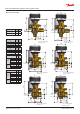
Data sheet | Thermostatic expansion valves, type TE 5 – TE 55
© Danfoss | DCS (sw) | 2019.01
DKRCC.PD.AB0.A7.02 | 32