
Technical Bulletin

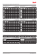


Capacity in kW. Range: -40 – 10 °C.
Opening superheat sh = 4 K
SI units R134a
Valve
type
Orice
no.
Cond.
temp.
[°C]
Evap. temp. [°C]
-40 -30 -20 -10 0 10
TE 5
0.5 25
2.59 3.33 4.16 5.00 5.65 5.72
01 25 4.76 6.12 7.65 9.18 10.3 10.4
02 25 6.69 8.60 10.7 12.8 14.4 14.4
03 25 8.55 11.0 13.8 16.5 18.6 18.7
04 25 11.5 14.9 18.7 22.5 25.4 25.4
TE 12
05 25 15.2 19.3 24.1 29.0 33.0 33.6
06 25
19.7 25.2 31.6 38.4 43.9 44.8
07 25 26.3 33.8 42.6 51.9 59.5 60.8
TE 20
08 25
30.2 39.1 49.3 59.8 67.8 68.3
09 25 34.8 45.4 58.0 71.5 82.4 84.0
TE 55
10 25
40.0 52.7 67.7 84.0 98.1 102
11 25 44.6 58.7 75.4 93.4 109 113
12 25 48.5 64.0 82.6 103 121 127
13 25 60.6 80.4 104 130 152 156
Subcooling correction factor, f
sub
Subcooling [K] 2 4 10 15 20 25 30
Correction factor 0.98 1.00 1.06 1.12 1.17 1.22 1.28
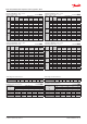
Capacity in TR. Range: -40 – 50 °F.
Opening superheat sh = 7.2 °F.
US units R134a
Valve
type
Orice
no.
Cond.
temp.
[°F]
Evap. temp. [°F]
-40 -20 0 20 40 50
TE 5
0.5 75 0.73 0.96 1.22 1.47 1.61 1.57
01 75 1.35 1.78 2.25 2.70 2.94 2.87
02 75 1.89 2.49 3.15 3.76 4.06 3.95
03 75 2.42 3.19 4.06 4.87 5.27 5.14
04 75
3.27 4.33 5.53 6.64 7.18 6.97
TE 12
05 75 4.29 5.61 7.12 8.59 9.42 9.26
06 75
5.57 7.32 9.36 11.4 12.6 12.4
07 75
7.47 9.85 12.7 15.5 17.1 16.8
TE 20
08 75 8.57 11.4 14.6 17.7 19.3 18.8
09 75
9.88 13.3 17.3 21.3 23.6 23.1
TE 55
10 75 11.4 15.4 20.2 25.2 28.4 28.1
11 75 12.7 17.2 22.5 28.0 31.5 31.1
12 75 13.8 18.8 24.7 31.0 35.2 34.9
13 75 17.3 23.6 31.2 39.0 43.9 43.2
Distributer correction factor, f
p
SI units R134a
Pressure drop
[bar]
∆p
Evap. temp. [°C]
-40 -30 -20 -10 0 10
Correction factor
0 1 1 1 1 1 1
1 0.93 0.93 0.92 0.92 0.90 0.87
1.5 0.90 0.89 0.88 0.87 0.84 0.79
2 0.86 0.85 0.84 0.82 0.79 0.71
Calculated at 32 °C condensing temperature.
Distributer correction factor, f
p
US units R134a
Pressure drop
[psi]
∆p
Evap. temp. [°F]
-40 -20 0 20 40 50
Correction factor
0 1 1 1 1 1 1
15 0.93 0.93 0.92 0.91 0.89 0.86
25 0.88 0.87 0.86 0.84 0.80 0.76
30 0.86 0.85 0.83 0.81 0.75 0.70
Calculated at 90 °F condensing temperature.
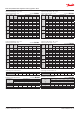
Capacity in kW. Range: -40 – 10 °C.
Opening superheat sh = 4 K
SI units R134a
Valve
type
Orice
no.
Cond.
temp.
[°C]
Evap. temp. [°C]
-40 -30 -20 -10 0 10
TE 5
0.5 35
2.65 3.42 4.34 5.36 6.35 7.03
01 35
4.86 6.29 7.98 9.85 11.6 12.8
02 35
6.81 8.83 11.2 13.8 16.2 17.7
03 35 8.70 11.3 14.3 17.6 20.8 22.9
04 35 11.6 15.2 19.3 24.0 28.4 31.1
TE 12
05 35 15.3 19.5 24.5 30.3 36.1 40.2
06 35 19.6 25.1 31.9 39.8 47.8 53.6
07 35 26.1 33.3 42.1 52.5 63.2 71.1
TE 20
08 35 30.3 39.2 50.0 62.3 74.4 82.4
09 35 34.1 44.4 57.3 72.6 88.3 99.3
TE 55
10 35 38.2 51.0 66.8 85.5 105 121
11 35 42.3 56.4 73.9 94.4 116 133
12 35
45.6 61.0 80.3 103 128 148
13 35 56.0 75.3 99.4 128 159 182
Capacity in TR. Range: -40 – 50 °F.
Opening superheat sh = 7.2 °F.
US units R134a
Valve
type
Orice
no.
Cond.
temp.
[°F]
Evap. temp. [°F]
-40 -20 0 20 40 50
TE 5
0.5 95 0.75 1.00 1.30 1.62 1.91 2.00
01 95 1.38 1.84 2.38 2.97 3.49 3.65
02 95
1.93 2.58 3.34 4.15 4.84 5.03
03 95
2.47 3.29 4.26 5.33 6.24 6.51
04 95 3.30 4.43 5.78 7.25 8.50 8.84
TE 12
05 95 4.35 5.67 7.31 9.17 10.9 11.4
06 95 5.57 7.34 9.54 12.1 14.5 15.2
07 95 7.42 9.70 12.6 15.9 19.1 20.2
TE 20
08 95 8.60 11.4 14.9 18.9 22.4 23.4
09 95 9.69 13.0 17.2 22.1 26.8 28.2
TE 55
10 95
10.8 14.9 20.1 26.6 32.1 34.3
11 95
12.0 16.5 22.2 28.9 35.4 37.7
12 95 113.0 17.9 24.2 31.6 39.1 41.9
13 95
15.9 22.1 29.9 39.3 48.5 51.7
Subcooling correction factor, f
sub
Subcooling [°F] 2 7 10 20 30 40 50
Correction factor 0.97 1.00 1.02 1.08 1.15 1.21 1.27
Data sheet | Thermostatic expansion valves, type TE 5 – TE 55
© Danfoss | DCS (sw) | 2019.01
DKRCC.PD.AB0.A7.02 | 30