
Technical Bulletin

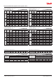


Capacity in TR. Range: -40 – 50 °F.
Opening superheat sh = 7.2 °F.
US units R513A
Valve
type
Orice
no.
Cond.
temp.
[°F]
Evap. temp. [°F]
-40 -20 0 20 40 50
TE 5
0.5 115 0.57 0.79 1.07 1.39 1.74 1.90
01 115
1.05 1.46 1.96 2.56 3.20 3.49
02 115 1.47 2.04 2.76 3.60 4.47 4.84
03 115
1.88 2.59 3.48 4.55 5.68 6.19
04 115
2.47 3.45 4.69 6.18 7.76 8.46
TE 12
05 115 3.04 4.07 5.37 6.98 8.83 9.75
06 115
3.83 5.19 6.94 9.15 11.7 13.0
07 115 5.11 6.80 8.95 11.6 14.9 16.6
TE 20
08 115 6.89 9.60 13.0 17.1 21.7 23.7
09 115 7.15 9.92 13.5 18.1 23.5 26.2
TE 55
10 115
7.45 11.0 15.7 21.7 28.5 31.9
11 115 8.16 12.0 17.2 23.7 31.2 34.8
12 115
8.69 12.8 18.4 25.6 34.0 38.1
13 115 10.4 15.5 22.3 31.2 41.5 46.5
Capacity in TR. Range: -40 – 50 °F.
Opening superheat sh = 7.2 °F.
US units R513A
Valve
type
Orice
no.
Cond.
temp.
[°F]
Evap. temp. [°F]
-40 -20 0 20 40 50
TE 5
0.5 135 0.54 0.75 1.01 1.32 1.68 1.87
01 135 0.98 1.37 1.85 2.44 3.10 3.43
02 135 1.37 1.91 2.60 3.42 4.34 4.79
03 135 1.75 2.42 3.26 4.28 5.44 6.03
04 135 2.28 3.19 4.35 5.79 7.43 8.25
TE 12
05 135
2.82 3.75 4.92 6.38 8.14 9.09
06 135
3.51 4.72 6.29 8.29 10.7 12.1
07 135
4.69 6.14 7.96 10.3 13.1 14.8
TE 20
08 135
6.29 8.72 11.8 15.5 19.9 22.2
09 135 6.43 8.82 11.9 15.9 20.9 23.7
TE 55
10 135 6.22 9.35 13.6 19.0 25.7 29.3
11 135 6.76 10.2 14.7 20.6 27.9 31.7
12 135 7.12 10.7 15.6 22.0 30.0 34.3
13 135 8.30 12.6 18.5 26.3 36.1 41.3
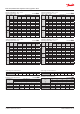
Capacity in kW. Range: -40 – 10 °C.
Opening superheat sh = 4 K
SI units R513A
Valve
type
Orice
no.
Cond.
temp.
[°C]
Evap. temp. [°C]
-40 -30 -20 -10 0 10
TE 5
0.5 45
2.03 2.72 3.57 4.56 5.66 6.69
01 45 3.72 5.0 6.56 8.40 10.4 12.3
02 45 5.20 7.01 9.21 11.8 14.5 17.0
03 45 6.65 8.89 11.6 14.9 18.5 21.8
04 45 8.78 11.9 15.7 20.2 25.2 29.7
TE 12
05 45 10.8 14.0 18.0 22.9 28.6 34.4
06 45
13.6 17.9 23.3 30.0 37.8 45.9
07 45 18.1 23.5 30.2 38.4 48.1 58.8
TE 20
08 45
24.5 33.0 43.5 56.1 70.3 83.7
09 45 25.5 34.2 45.3 59.2 75.8 92.6
TE 55
10 45
26.7 37.8 52.2 70.3 91.4 113
11 45
29.2 41.4 57.2 76.9 100 123
12 45 31.2 44.3 61.4 83.0 109 135
13 45
37.3 53.3 74.3 101 133 165
Capacity in kW. Range: -40 – 10 °C.
Opening superheat sh = 4 K
SI units R513A
Valve
type
Orice
no.
Cond.
temp.
[°C]
Evap. temp. [°C]
-40 -30 -20 -10 0 10
TE 5
0.5 55 1.92 2.58 3.40 4.37 5.49 6.64
01 55 3.51 4.73 6.24 8.05 10.1 12.2
02 55 4.90 6.63 8.76 11.3 14.2 17.0
03 55 6.27 8.39 11.0 14.2 17.8 21.5
04 55 8.18 11.1 14.7 19.1 24.2 29.4
TE 12
05 55 10.1 13.1 16.8 21.3 26.7 32.7
06 55 12.6 16.5 21.4 27.6 35.0 43.5
07 55 16.9 21.6 27.3 34.5 43.3 53.6
TE 20
08 55 22.6 30.4 40.0 51.6 65.3 79.9
09 55
23.2 30.9 40.7 53.0 68.2 85.7
TE 55
10 55
22.8 32.9 46.0 62.7 83.1 106
11 55 24.9 35.8 50.0 68.2 90.3 115
12 55
26.2 37.9 53.1 72.8 97.1 124
13 55 30.7 44.7 63.1 87.0 117 150
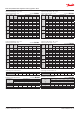
Subcooling correction factor, f
sub
Subcooling [K] 2 4 10 15 20 25 30
Correction factor 0.98 1.00 1.07 1.13 1.18 1.24 1.31
Distributer correction factor, f
p
SI units R513A
Pressure drop
[bar]
∆p
Evap. temp. [°C]
-40 -30 -20 -10 0 10
Correction factor
0 1 1 1 1 1 1
1 0.94 0.93 0.93 0.92 0.90 0.87
1.5 0.90 0.90 0.89 0.88 0.85 0.80
2 0.87 0.86 0.85 0.83 0.79 0.72
Calculated at 32 °C condensing temperature.
Distributer correction factor, f
p
US units R513A
Pressure drop
[psi]
∆p
Evap. temp. [°F]
-40 -20 0 20 40 50
Correction factor
0 1 1 1 1 1 1
15 0.93 0.93 0.92 0.91 0.89 0.87
25 0.89 0.88 0.87 0.85 0.81 0.77
30 0.86 0.85 0.84 0.82 0.76 0.71
Calculated at 90 °F condensing temperature.
Subcooling correction factor, f
sub
Subcooling [°F] 2 7 10 20 30 40 50
Correction factor 0.97 1.00 1.02 1.08 1.15 1.21 1.29
Data sheet | Thermostatic expansion valves, type TE 5 – TE 55
© Danfoss | DCS (sw) | 2019.01
DKRCC.PD.AB0.A7.02 | 29