
Technical Bulletin

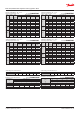


Capacity in kW. Range: -60 – -25 °C.
Opening superheat sh = 4 K SI units R404A/R507
Valve
type
Orice
no.
Cond.
temp.
[°C]
Evap. temp. [°C]
-60 -50 -40 -30 -25
TE 5
0.5 40
1.69 2.48 3.51 4.75 5.43
01 40 3.06 4.53 6.44 8.76 10.0
02 40 4.21 6.29 9.03 12.4 14.2
03 40 5.17 7.75 11.2 15.4 17.7
04 40 6.52 9.96 14.7 20.8 24.1
TE 12
05 40
8.10 12.0 17.4 24.2 28.0
06 40
9.70 14.6 21.5 30.7 36.0
07 40 12.0 18.1 26.6 37.9 44.6
TE 55
9B 40 15.8 23.1 33.0 45.1 51.8
10 40 17.7 26.2 38.2 54.0 63.3
11 40
19.2 28.6 41.6 58.8 68.9
12 40
20.4 30.3 44.2 62.7 73.6
13 40 23.8 35.7 52.3 74.8 88.3
Capacity in TR. Range: -75 – -15 °F.
Opening superheat sh = 7.2 °F. US units R404A/R507
Valve
type
Orice
no.
Cond.
temp.
[°F]
Evap. temp. [°F]
-75 -60 -45 -30 -15
TE 5
0.5 105 0.49 0.67 0.90 1.18 1.49
01 105 0.88 1.22 1.65 2.17 2.75
02 105 1.21 1.70 2.31 3.05 3.88
03 105 1.49 2.09 2.86 3.80 4.86
04 105
1.88 2.68 3.73 5.06 6.60
TE 12
05 105 2.33 3.25 4.43 5.91 7.66
06 105
2.79 3.93 5.46 7.41 9.80
07 105
3.44 4.84 6.72 9.13 12.1
TE 55
9B 105 4.52 6.23 8.43 11.1 14.2
10 105
5.06 7.05 9.68 13.1 17.2
11 105 5.51 7.68 10.6 14.2 18.7
12 105 5.83 8.14 11.2 15.1 20.0
13 105 6.81 9.56 13.2 18.0 23.9
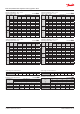
Capacity in kW. Range: -60 – -25 °C.
Opening superheat sh = 4 K SI units R404A/R507
Valve
type
Orice
no.
Cond.
temp.
[°C]
Evap. temp. [°C]
-60 -50 -40 -30 -25
TE 5
0.5 50 1.47 2.18 3.13 4.29 4.95
01 50 2.64 3.97 5.73 7.92 9.15
02 50
3.61 5.50 8.04 11.2 13.0
03 50 4.36 6.66 9.81 13.8 16.1
04 50
5.35 8.39 12.7 18.4 21.7
TE 12
05 50
6.68 10.1 14.9 21.1 24.8
06 50 7.75 12.0 18.1 26.3 31.2
07 50 9.28 14.4 21.6 31.5 37.4
TE 55
9B 50 12.7 18.9 27.5 38.5 44.6
10 50 13.8 21.0 31.1 44.7 52.8
11 50 14.9 22.7 33.6 48.3 57.0
12 50 15.6 23.8 35.4 51.0 60.3
13 50 17.8 27.4 41.0 59.5 70.8
Capacity in TR. Range: -75 – -15 °F.
Opening superheat sh = 7.2 °F. US units R404A/R507
Valve
type
Orice
no.
Cond.
temp.
[°F]
Evap. temp. [°F]
-75 -60 -45 -30 -15
TE 5
0.5 125 0.41 0.58 0.79 1.04 1.33
01 125 0.74 1.05 1.44 1.92 2.47
02 125
1.02 1.45 2.01 2.70 3.50
03 125
1.23 1.75 2.44 3.30 4.31
04 125 1.50 2.19 3.13 4.34 5.81
TE 12
05 125 1.87 2.65 3.70 5.02 6.61
06 125 2.15 3.12 4.42 6.13 8.27
07 125 2.56 3.71 5.25 7.29 9.85
TE 55
9B 125 3.51 4.93 6.80 9.14 11.9
10 125 3.81 5.43 7.60 10.4 13.9
11 125 4.11 5.87 8.21 11.2 15.0
12 125 4.30 6.15 8.61 11.8 15.9
13 125 4.89 7.04 9.92 13.7 18.5
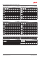
Subcooling correction factor, f
sub
Subcooling [K] 2 4 10 15 20 25 30
Correction factor 0.97 1.00 1.09 1.16 1.23 1.30 1.37
Distributer correction factor, f
p
SI units R404A/R507
Pressure drop
[bar]
∆p
Evap. temp. [°C]
-60 -50 -40 -30 -25
Correction factor
0 1 1 1 1 1
1 0.97 0.96 0.96 0.96 0.96
1.5 0.95 0.95 0.94 0.94 0.94
2 0.93 0.93 0.92 0.92 0.92
Calculated at 32 °C condensing temperature.
Distributer correction factor, f
p
US units R404A/R507
Pressure drop
[psi]
∆p
Evap. temp. [°F]
-75 -60 -45 -30 -15
Correction factor
0 1 1 1 1 1
15 0.96 0.96 0.96 0.96 0.96
25 0.94 0.94 0.94 0.93 0.93
30 0.93 0.93 0.92 0.92 0.92
Calculated at 90 °F condensing temperature.
Subcooling correction factor, f
sub
Subcooling [°F] 2 7 10 20 30 40 50
Correction factor 0.96 1.00 1.03 1.11 1.20 1.28 1.37
Data sheet | Thermostatic expansion valves, type TE 5 – TE 55
© Danfoss | DCS (sw) | 2019.01
DKRCC.PD.AB0.A7.02 | 23