
Technical Bulletin

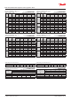


Capacity in kW. Range: -40 – 10 °C.
Opening superheat sh = 4 K
SI units R404A/R507
Valve
type
Orice
no.
Cond.
temp.
[°C]
Evap. temp. [°C]
-40 -30 -20 -10 0 10
TE 5
0.5 45
3.08 4.11 5.32 6.67 8.02 9.05
01 45 5.65 7.57 9.81 12.3 14.7 16.5
02 45
7.94 10.7 13.8 17.2 20.4 22.7
03 45
9.85 13.2 17.2 21.6 25.9 29.0
04 45 13.0 17.7 23.3 29.4 35.4 39.4
TE 12
05 45
16.1 21.9 29.1 37.8 47.4 55.3
06 45 19.1 26.4 35.6 46.9 59.6 70.1
07 45 23.1 31.4 42.0 55.7 71.9 86.8
TE 20
08 45 28.0 38.4 51.3 66.6 82.8 95.2
09 45 29.5 40.7 55.0 73.0 93.2 110
TE 55
10 45 33.5 48.5 67.4 90.6 117 140
11 45 36.2 52.5 72.9 97.9 126 150
12 45 38.3 55.5 77.5 104 136 165
13 45
44.6 65.3 91.8 125 162 196
Subcooling correction factor, f
sub
Subcooling [K] 2 4 10 15 20 25 30
Correction factor 0.97 1.00 1.09 1.16 1.23 1.30 1.37
Capacity in TR. Range: -40 – 50 °F.
Opening superheat sh = 7.2 °F.
US units R404A/R507
Valve
type
Orice
no.
Cond.
temp.
[°F]
Evap. temp. [°F]
-40 -20 0 20 40 50
TE 5
0.5 115 0.86 1.18 1.57 2.00 2.41 2.56
01 115
1.58 2.18 2.90 3.69 4.42 4.69
02 115 2.22 3.07 4.07 5.15 6.11 6.43
03 115
2.75 3.81 5.07 6.48 7.77 8.21
04 115 3.63 5.11 6.88 8.84 10.6 11.2
TE 12
05 115 4.48 6.29 8.60 11.4 14.4 15.6
06 115 5.29 7.59 10.6 14.3 18.2 19.8
07 115
6.41 8.97 12.4 16.9 22.1 24.3
TE 20
08 115 7.79 11.1 15.2 20.1 25.1 26.9
09 115
8.19 11.7 16.3 22.2 28.5 31.1
TE 55
10 115
9.25 14.0 20.1 27.6 35.9 39.5
11 115 10.0 15.1 21.7 29.8 38.6 42.4
12 115
10.6 16.0 23.1 32.0 41.9 46.3
13 115 12.3 18.6 27.3 38.0 49.9 55.1
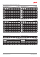
Distributer correction factor, f
p
SI units R404A/R507
Pressure drop
[bar]
∆p
Evap. temp. [°C]
-40 -30 -20 -10 0 10
Correction factor
0 1 1 1 1 1 1
1 0.96 0.96 0.96 0.95 0.94 0.92
1.5 0.94 0.94 0.94 0.93 0.91 0.88
2 0.92 0.92 0.91 0.90 0.88 0.84
Calculated at 32 °C condensing temperature.
Distributer correction factor, f
p
US units R404A/R507
Pressure drop
[psi]
∆p
Evap. temp. [°C]
-40 -20 0 20 40 50
Correction factor
0 1 1 1 1 1 1
15 0.96 0.96 0.96 0.95 0.93 0.92
25 0.94 0.93 0.92 0.91 0.89 0.87
30 0.92 0.92 0.91 0.89 0.86 0.84
Calculated at 90 °F condensing temperature.
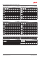
Capacity in kW. Range: -40 – 10 °C.
Opening superheat sh = 4 K
SI units R404A/R507
Valve
type
Orice
no.
Cond.
temp.
[°C]
Evap. temp. [°C]
-40 -30 -20 -10 0 10
TE 5
0.5 55
2.60 3.50 4.57 5.83 7.20 8.50
01 55
4.76 6.44 8.45 10.8 13.3 15.7
02 55
6.69 9.10 11.9 15.2 18.6 21.7
03 55 8.24 11.1 14.6 18.7 23.2 27.3
04 55 10.8 14.9 19.8 25.6 31.9 37.5
TE 12
05 55 13.3 16.0 23.8 31.1 40.0 49.4
06 55 15.5 21.4 28.9 38.4 50.3 63.1
07 55 18.6 24.9 33.0 43.4 56.9 72.4
TE 20
08 55 23.1 31.5 42.1 55.4 71.1 86.8
09 55 23.8 32.6 43.9 58.6 77.2 97.3
TE 55
10 55 25.7 38.1 53.8 73.7 97.8 124
11 55 27.7 41.0 57.8 79.0 105 132
12 55
28.9 42.9 60.8 83.6 112 142
13 55 33.1 49.6 70.7 97.9 131 168
Capacity in TR. Range: -40 – 50 °F.
Opening superheat sh = 7.2 °F.
US units R404A/R507
Valve
type
Orice
no.
Cond.
temp.
[°F]
Evap. temp. [°F]
-40 -20 0 20 40 50
TE 5
0.5 135 0.70 0.98 1.31 1.71 2.14 2.34
01 135 1.29 1.80 2.42 3.16 3.95 4.31
02 135
1.81 2.55 3.43 4.45 5.52 5.98
03 135
2.22 3.10 4.18 5.47 6.87 7.50
04 135 2.90 4.14 5.67 7.50 9.47 10.3
TE 12
05 135 3.57 4.98 6.77 9.07 11.9 13.4
06 135 4.15 5.93 8.24 11.3 15.1 17.1
07 135 4.99 6.87 9.33 12.6 16.9 19.3
TE 20
08 135 6.21 8.76 12.0 16.2 21.2 23.7
09 135 6.38 9.00 12.5 17.2 23.1 26.3
TE 55
10 135
6.78 10.5 15.4 21.8 29.5 33.5
11 135
7.29 11.3 16.5 23.3 31.5 35.7
12 135 7.61 11.8 17.4 24.6 33.6 38.4
13 135
8.67 13.6 20.2 28.8 39.5 45.2
Subcooling correction factor, f
sub
Subcooling [°F] 2 7 10 20 30 40 50
Correction factor 0.96 1.00 1.03 1.11 1.20 1.28 1.37
Data sheet | Thermostatic expansion valves, type TE 5 – TE 55
© Danfoss | DCS (sw) | 2019.01
DKRCC.PD.AB0.A7.02 | 21