
Technical Bulletin
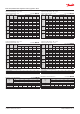


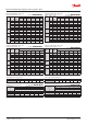

Capacity in kW. Range: -40 – 10 °C.
Opening superheat sh = 4 K
SI units R404A/R507
Valve
type
Orice
no.
Cond.
temp.
[°C]
Evap. temp. [°C]
-40 -30 -20 -10 0 10
TE 5
0.5 25
3.68 4.77 5.91 6.93 7.54 7.30
01 25
6.76 8.76 10.8 12.7 13.7 13.2
02 25 9.49 12.3 15.1 17.6 18.8 17.9
03 25
12.0 15.6 19.4 22.6 24.4 23.3
04 25 16.1 21.1 26.3 30.8 33.1 31.2
TE 12
05 25 20.7 28.0 36.0 43.9 48.9 47.2
06 25 24.9 34.1 44.5 55.0 61.7 59.6
07 25 32.5 43.9 57.6 71.9 81.4 78.3
TE 20
08 25 35.7 48.4 62.2 75.2 82.9 79.7
09 25 39.5 54.2 71.3 88.4 100 97.0
TE 55
10 25 46.5 64.9 86.1 108 124 125
11 25
51.1 71.2 94.4 118 136 135
12 25 54.8 76.8 103 130 151 152
13 25
66.5 93.7 126 159 183 181
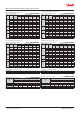
Subcooling correction factor, f
sub
Subcooling [K] 2 4 10 15 20 25 30
Correction factor 0.97 1.00 1.09 1.16 1.23 1.30 1.37
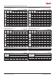
Capacity in TR. Range: -40 – 50 °F.
Opening superheat sh = 7.2 °F.
US units R404A/R507
Valve
type
Orice
no.
Cond.
temp.
[°F]
Evap. temp. [°F]
-40 -20 0 20 40 50
TE 5
0.5 75 1.05 1.39 1.74 2.03 2.11 2.02
01 75
1.93 2.56 3.20 3.70 3.83 3.65
02 75 2.71 3.58 4.45 5.11 5.21 4.93
03 75
3.42 4.56 5.71 6.61 6.78 6.43
04 75 4.59 6.17 7.76 8.98 9.15 8.62
TE 12
05 75 5.94 8.23 10.8 13.0 13.8 13.1
06 75 7.14 10.1 13.4 16.4 17.4 16.5
07 75
9.36 13.1 17.4 21.6 22.9 21.7
TE 20
08 75 10.2 14.2 18.6 22.2 23.2 22.0
09 75
11.3 16.1 21.5 26.4 28.2 26.8
TE 55
10 75
13.4 19.2 26.0 32.4 35.6 34.6
11 75 14.7 21.1 28.5 35.5 38.8 37.5
12 75
15.8 22.8 31.1 39.2 43.4 42.2
13 75 19.2 27.9 38.2 47.9 52.3 50.3
Distributer correction factor, f
p
SI units R404A/R507
Pressure drop
[bar]
∆p
Evap. temp. [°C]
-40 -30 -20 -10 0 10
Correction factor
0 1 1 1 1 1 1
1 0.96 0.96 0.96 0.95 0.94 0.92
1.5 0.94 0.94 0.94 0.93 0.91 0.88
2 0.92 0.92 0.91 0.90 0.88 0.84
Calculated at 32 °C condensing temperature.
Distributer correction factor, f
p
US units R404A/R507
Pressure drop
[psi]
∆p
Evap. temp. [°F]
-40 -20 0 20 40 50
Correction factor
0 1 1 1 1 1 1
15 0.96 0.96 0.96 0.95 0.93 0.92
25 0.94 0.93 0.92 0.91 0.89 0.87
30 0.92 0.92 0.91 0.89 0.86 0.84
Calculated at 90 °F condensing temperature.
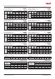
Capacity in kW. Range: -40 – 10 °C.
Opening superheat sh = 4 K
SI units R404A/R507
Valve
type
Orice
no.
Cond.
temp.
[°C]
Evap. temp. [°C]
-40 -30 -20 -10 0 10
TE 5
0.5 35
3.45 4.55 5.78 7.05 8.12 8.61
01 35
6.34 8.37 10.6 12.9 14.8 15.6
02 35
8.90 11.8 14.9 18.0 20.4 21.3
03 35 11.1 14.8 18.8 22.9 26.3 28.0
04 35 14.9 19.9 25.5 31.2 35.7 37.1
TE 12
05 35 18.7 25.3 33.3 42.3 50.5 54.4
06 35 22.3 30.7 41.0 52.7 63.6 68.7
07 35 27.8 37.9 50.7 66.0 81.2 89.1
TE 20
08 35 32.4 44.3 58.4 73.6 86.9 92.6
09 35 34.9 48.2 64.6 83.5 101 110
TE 55
10 35 40.6 57.7 78.7 103 126 141
11 35 44.3 62.9 85.7 112 137 153
12 35
47.1 67.2 92.1 121 150 170
13 35 56.0 80.5 110 146 181 203
Capacity in TR. Range: -40 – 50 °F.
Opening superheat sh = 7.2 °F.
US units R404A/R507
Valve
type
Orice
no.
Cond.
temp.
[°F]
Evap. temp. [°F]
-40 -20 0 20 40 50
TE 5
0.5 95 0.98 1.33 1.72 2.11 2.39 2.44
01 95 1.80 2.44 3.16 3.87 4.37 4.44
02 95
2.53 3.43 4.42 5.37 5.98 6.04
03 95
3.16 4.31 5.60 6.86 7.71 7.80
04 95 4.21 5.81 7.60 9.34 10.5 10.5
TE 12
05 95 5.29 7.42 10.0 12.9 15.1 15.4
06 95 6.32 9.02 12.4 16.1 19.0 19.5
07 95 7.90 11.1 15.3 20.3 24.5 25.3
TE 20
08 95 9.18 13.0 17.5 22.3 25.8 26.3
09 95 9.89 14.1 19.5 25.5 30.4 31.3
TE 55
10 95
11.5 17.0 23.8 31.5 38.3 40.1
11 95
12.6 18.5 25.9 34.2 41.4 43.4
12 95 13.4 19.8 27.9 37.2 45.7 48.2
13 95
15.9 23.7 33.6 45.0 54.9 57.5
Subcooling correction factor, f
sub
Subcooling [°F] 2 7 10 20 30 40 50
Correction factor 0.96 1.00 1.03 1.11 1.20 1.28 1.37
Data sheet | Thermostatic expansion valves, type TE 5 – TE 55
© Danfoss | DCS (sw) | 2019.01
DKRCC.PD.AB0.A7.02 | 20