
Install Instructions

Installation continued
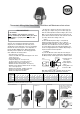
The Series 30 MR valves are not intended to provide final tempera-
ture control at the fixtures or point of use. Use Series 30 HR/HV
valves that meet ASSE 1016 for these applications.
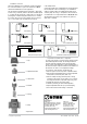
The valve should be installed below the storage tank or water heater
as shown in Fig. 3 wherever possible. If the valve is installed adjacent
to, or higher than the storage tank or water heater, it is important to
prevent gravity circulation during times where there is no consump-
tion of water. This is done by various methods such as a heat trap
loop or a check valve in the cold water feed line as shown
in the examples below.
A check valve should also be installed whenever a high tempera-ture
(uncontrolled) water outlet is included (Fig. 4). For installation of
a TMV in a system providing recirculated tempered water using a
circulation pump refer to Fig. 6. An aquastat to limit circulation of
recirculated water is not required with Series 30 MR/HR/HV valves.
The thermostatic mixing valve can be installed in any position i.e.
upside down or sideways.
3
54
21
7
Series 30 MR
6
© Copyright. All rights reserved. Art.nr. 98140120 Ritn.nr. 9097 Utg. PD5
Inspection and maintenance – important!
To ensure proper function, a licensed contractor should verify the
mixed outlet temperature annually. The following maintenance
procedure should be performed each year and at times when
increase in water outlet temperature is observed. Replacement of
the valve insert may be required if maintenance and calibration of
the valve does not result in correct temperature readings.
To clean and/or restore the valve, shut off water and:
1. Remove cap (item 1) and note position of adjustment wheel.
2. Remove wheel and disassemble valve by removing adjustment
bonnet (item 2) and internal parts. (items 3–6).
3. Remove carefully all scaling (calcium deposits) or foreign
particles from all parts. Do not use sharp tools or scratch sur-
faces. Regrease all internal components using silicon grease.
4. Assemble the valve and restore water supply.
5. Calibrate by measuring the mixed outlet temperature.
6. Replace adjustment wheel and cap to prevent tampering.
7. Record service date and valve setting on valve label.
Primary-Secondary Pumping
Central Mixing
Central Mixing Radiant Floor Heating Recirculated Domestic Water
Central Mixing Central Mixing
Boiler Return Water Temperature Control
* Spare Parts
6 – Body
5 – Spring*
4 – Shuttle*
3 – Thermostat*
2 – Adjustment bonnet*
1 – Cap
8
Distributed by:
Danfoss Inc.
6711 Mississauga Road · Suite 410
Mississauga, ON, L5N 2W3 Canada
Telephone: (905) 285 - 2050
Fax: (905) 285 - 2055
E-mail: heatinginfo@danfoss.com
www.na.heating.danfoss.com
Distributed by:
Danfoss Inc.
7941 Corporate Drive
Baltimore, MD USA 21236
Tel. (443) 512 - 0266
Fax. (443) 512 - 0270
E-mail: heatinginfo@danfoss.com
www.na.heating.danfoss.com