
Submittal Sheet
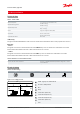
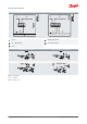
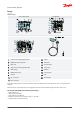
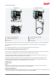
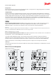
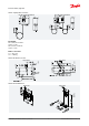
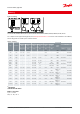
Table Of Contents

1.
2.
3.
5.
7.
8.
9.
10.
11.
12.
13.
14.
15.
16.
18.
19.
30.
Design
Table 4: Design
Pressure switch, type KP
KP 1, KP 2, KP 5
FW
FW
KP 15, KP 25 are
KP 1, KP 2, KP 5, KP 15, KP 25, KP 7W, KP 7B, KP 17W, capillary tube
FW
Low pressure setting spindle, (LP)
Dierential setting spindle
Main arm
High pressure setting spindle, (HP)
Main spring
Dierential spring
Bellows
LP connection
HP connection
Switch
Terminals
Earth terminal
Cable entry
Tumbler
Locking plate
Arm
Reset button
The switch in the KP has a snap-action function where the bellows move only when the cut-in or cut-out value is
reached.
The bellows are connected to the low or high pressure side of the system through connection (10) or (11).
The design of the KP gives the following advantages:
• high contact load
• ultra-short bounce time
• high resistance to pulsation
• vibration resistance up to 4 g in the range 0 – 1000 Hz
• long mechanical and electrical life
Pressure switch, Type KP
© Danfoss | Climate Solutions | 2021.02 AI216886432258en-001101 | 4