
Submittal Sheet
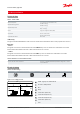
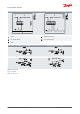
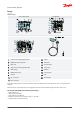
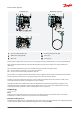
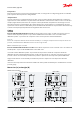
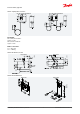
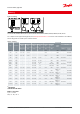
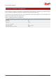
Table Of Contents

4
2
1 4 2 1
Danfoss
A60-1032.10
A
B
C
D
E
F
G
H
I
I
A
B
C
D
E
F
G
H
I
SPDT - signal pole double throw
Pressure / Temperature
Rise
Drop
Load Cut-in (term.1-4)
Load Cut-out (term.1-2)
Load Cut-out (term.1-4)
Load Cut-in (term.1-2)
Line
Product specication
Technical data
Table 1: Technical data
Features
Values
Ambient temperature
-40 – 149 °F (175 °F for maximum 2 hours)
Maximum working pressure
LP: MWP = 245 psig
HP: MWP = 465 psig
Maximum test pressure
LP: p
e
= 285 psig
HP: p
e
= 510 psig
Switch
Single pole changeover switch (SPDT)
Contact load
120 V AC: 16 FLA, 96 LRA
240 V AC: 8 FLA, 48 LRA
240 V DC: 12 W pilot duty
Terminal D, dual switches
240 V, 50 VA
Cable entry
Integral 1⁄2 in female NPSM swivel cable connector allows direct attachment of 1⁄2 in male pipe thread connector.
Enclosure
~NEMA 1
This grade of enclosure is obtained when the units without top cover are mounted on a at surface or bracket.
The bracket must be xed to the unit so that all unused holes are covered.
~ NEMA 2
This grade of enclosure is obtained when the units with top cover are mounted on a at surface or bracket.
The bracket must be xed to the unit so that all unused holes are covered
Table 2: Materials in contact with the medium
Control type
Material
KP 1, KP 2, KP 5, KP 7, KP 15, KP 17, KP 25
Tin bronze, no. CW452K, EN 1652 Nickel plated free cutting steel, no. 1.0737 /
1.0718 to EN 10277
KP with cap. tube
Copper SF-Cu, no. 2.0090 to DIN 1787
Electrical wiring
Table 3: Electrical wiring
Load
Signal option
Bellows movement on pressure rise
Bellows movement on pressure drop
Figure 1: Low or high pressure
Pressure switch, Type KP
© Danfoss | Climate Solutions | 2021.02 AI216886432258en-001101 | 2