
User's Manual


Doc. No.
Rev.
Date
DRAFT
1.01
2012-01-27
Damm Cellular Systems A/S, Denmark
TetraFlex
®
7.5 Manual - SB421
TetraFlex® 7.5
Manual
1-15
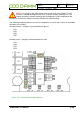
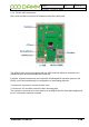
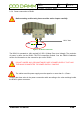
J40 Temperature switch
Figure 1-13: Interconnection Module
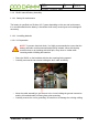
1.1.7 External -48 battery kit (option) connection block
The 3 screw connection block for -48V DC, 0 and ground is located on the inner right side of
the SB421 housing.
The SB421 is operated at -48V nominal DC (SELV) derived from the internal power supply.
An internal or external battery pack may be connected for backup purposes.
In case of using an external battery pack; the plus pole of the battery pack shall be grounded
with a 5mm
2
yellow/green wire.
Note: In case of using an external battery supply where the plus pole
not is connected to ground then the connection shall include a
disconnection device which disconnects both poles simultaneously,
otherwise there shall be a disconnection device, inserted in the
connection to the minus pole.
The external battery pack consists of a DIN-rail containing a 10A circuit breaker, a 3-pol
terminal strip, a 4-pol modular coupler and the necessary cabling.
The DIN-rail must be mounted as close to the external battery as possible.
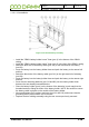
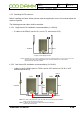
When delivered, the temperature sensor cable is terminated with a 4-pol modular connector.
Please cut the connector and mount the wires in the LSA block of the LAN/WAN connection
module according to this:
SB421 Temperature
J8A Sensor Cable
Pin# Function Color
1 Gnd. Yellow
2 +5V Brown
3 /Data Red
4 Data Blue
Figure 1-14: Temperature sensor