
User's Manual

Doc. No.
Rev.
Date
DRAFT
1.01
2012-01-27
Damm Cellular Systems A/S, Denmark
TetraFlex
®
7.5 Manual - SB421
TetraFlex® 7.5
Manual
1-5
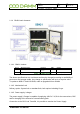
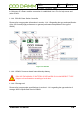
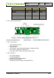
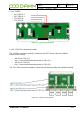
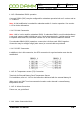
1.1.4.4.3 BSC connections
Connections
o TR1 and TR2 LAN to Interconnection board (J31)
o LAN / Wan to Interconnection board (J32)
o I/O for PS etc. (J30)
o USB1 for Node Dongle (J33)
o USB2 for service and maintenance (J50)
o VGA for service and maintenance (J51)
o LAN for service and maintenance (J52)
o CF socket (J201)
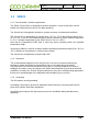
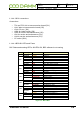
1.1.4.4.4 BSC421 LED’s and Fuses
BSC Status and warning LED’s: All LED’s ON, BSC software is not running
Group
Activity
LED
LED on Means
ALL
All LED’s ON, BSC SW is not running
BSC
POWER
Yellow
Power On
ACTIVE
Green
BSC Active
NETWORK
Red
No Ethernet
BSS
Red
No connection to BSS
BSC
Red
No connection to redundant BSC
ALARM
Red
Other BSC alarm present
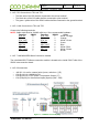
PS
LINK
Yellow
Connected to PS
MAINS
Green
Mains present
CHARGE
Green
Battery is charging
DISCH
Red
Battery is discharging
ALARM
Red
PS alarm
TR1
LINK
Yellow
Connection to BS421_1
ACTIVE
Green
BS421 active. (Tetra mode TX on)
ALARM
Red Steady
Blocking alarm
Red Flash
Non-blocking alarm
TR2
LINK
Yellow
Connection to BS421_2
ACTIVE
Green
BS421 active. (Tetra mode TX on)
ALARM
Red Steady
Blocking alarm
Red Flash
Non-blocking alarm
TR3
LINK
Yellow
Connection to BS421_3
ACTIVE
Green
BS421 active. (Tetra mode TX on)
ALARM
Red Steady
Blocking alarm
Red Flash
Non-blocking alarm
TR4
LINK
Yellow
Connection to BS421_4
ACTIVE
Green
BS421 active. (Tetra mode TX on)
ALARM
Red Steady
Blocking alarm
Red Flash
Non-blocking alarm
Figure 1-3: BSC LED's