
User`s manual

Spyder3 S3-14 and S3-24 User's Manual 87
Teledyne DALSA 03-032-20117-00
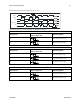
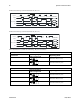
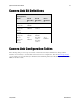
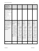
Camera Link Bit Definitions
BASE
Configuration
T0
Mode
Port A
Bits 0 thru
7
Port B
Bits 0 thru
7
Port C
Bits 0 thru
7
Mode 0
1 Tap 8 bit
Tap 1
LSB..Bit 7
xxxxxxx
xxxxxxx
Mode 1
1 Tap n bit
Where
n=10,12
Tap 1
LSB..Bit 7
Tap 1 Bits
8,9,10,11,
xxxxxxx
Mode 2
2 Tap 8 bit
Tap 1
LSB..Bit 7
Tap 2
LSB..Bit7
xxxxxxx
Mode 3
2 Tap n bit
Where
n=10,12
Tap 1
LSB..Bit 7
Tap 1 Bits
8,9,10,11,
Tap 2 Bits
8,9,10,11
Tap 2
LSB..Bit 7
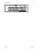
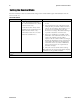
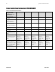
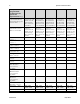
Camera Link Configuration Tables
The following table provides tap reconstruction information. Teledyne DALSA is working with the
machine vision industry to use this table as the basis for auto configuration. Visit the Knowledge Center
on our website, and view the Teledyne DALSA Camera Link Implementation Road Map document, 03-32-
00450, for further details.