
User`s manual

Spyder3 S3-14 and S3-24 User's Manual 49
Teledyne DALSA 03-032-20117-00
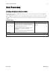
Digital Processing
To optimize camera performance, digital signal processing should be completed after any analog
adjustments.
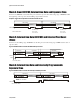
1. Fixed pattern noise (FPN) calibration (calculated using the ccf command) is used to subtract away
individual pixel dark current.
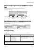
2. The digital offset (sdo comm and ) enables the su btraction of the ―artificial‖ A/ D offset (the analog
offset) so that app lication of the PRNU coefficient d oesn’t result in artifacts at low light levels d ue to
the offset value. You may want to set the sdo value if you are not using FPN correction but want to
perform PRNU correction.
3. Photo-Response Non-Uniformity (PRNU) coefficients (calculated using the ccp or cpa commands)
are used to correct the difference in responsivity of individual pixels (i.e. given the same amount of
light different pixels will charge up at different rates) and the change in light intensity across the
image either because of the light source or due to optical aberrations (e.g. there may be more light in
the center of the image). PRNU coefficients are multipliers and are defined to be of a value greater
than or equal to 1. This ensures that all pixels will saturate together.
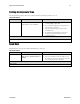
4. Background subtract (ssb command) and system (digital) gain (ssg command) are used to increase
image contrast after FPN and PRNU calibration. It is useful for systems that process 8-bit data but
want to take ad vantage of the cam era’s 12 bit d igital p rocessing chain. For example, if you find that
your image is consistently between 128 and 255 DN(8 bit), you can subtract off 128 (ssb 2048) and
then multiply by 2 (ssg 0 8192) to get an output range from 0 to 255.
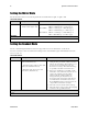
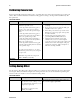
Analog Signal Processing: Setting Analog Gain and Offset
All analog signal processing chain commands should be performed prior to FPN and PRN U calibration
and prior to digital signal processing commands.
Note: This command will invalidate the LUT calibration for the 4k model of camera. Use the ssg
command instead.
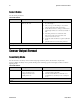
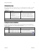
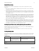
Setting Analog Gain
Sets the camera’s analog gain value. Analog gain is multiplie d by the analog signal to increase the signal
strength before the A/ D conversion. It is used to take advantage of the full dynamic range of the A/ D
converter.
Camera Link Command
Parameter
Description
Notes
sag t f
t Tap selection. Use 0 for all taps or 1
to 2 for individual tap selection
f Gain value in a range from –10 to
+10dB.
To return the current analog gain setting, use the
command gcp or get sag.
Example
sag 0 5.2