
User`s manual

34 Spyder3 S3-14 and S3-24 User's Manual
03-032-20117-00 Teledyne DALSA
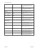
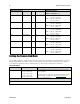
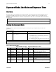
Mode Configuration
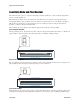
Readout Direction
Command
Models
Taps
Bit Depth
smm 0 increment =1
smm 1 increment = -1
clm 2
S3-24-01K40
2
8
smm 0 = CL tap 1 (1-512)
CL tap 2 (513-1024)
smm 1 = CL tap 1 (1024-513)
CL tap 2 (512-1)
S3-24-02K40
2
smm 0 = CL tap 1 (1-1024)
CL tap 2 (1025-2048)
smm 1 = CL tap 1 (2048-1025)
CL tap 2 (1024-1)
S3-24-04k-40
2
smm 0 = CL tap 1 (1-2048)
CL tap 2 (2049-4096)
smm 1 = CL tap 1 (4096-2049)
CL tap 2 (2048-1)
clm 3
S3-24-01K40
2
12
smm 0 = CL tap 1 (1-512)
CL tap 2 (513-1024)
smm 1 = CL tap 1 (1024-513)
CL tap 2 (512-1)
S3-24-02K40
2
smm 0 = CL tap 1 (1-1024)
CL tap 2 (1025-2048)
smm 1 = CL tap 1 (2048-1025)
CL tap 2 (1024-1)
S3-24-04k-40
2
smm 0 = CL tap 1 (1-2048)
CL tap 2 (2049-4096)
smm 1 = CL tap 1 (4096-2049)
CL tap 2 (2048-1)
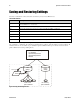
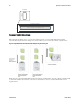
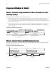
Setting the Camera Link Mode
Use the clm command to select the Camera Link configuration, the number of Camera Link taps, and the
data bit depth. Refer to the tables on the previous page to determine which configurations are valid for
your camera model and how this command relates to other camera configuration commands
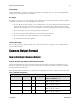
Camera Link Command
Parameter
Description
Notes
clm m
Output mode to use:
0: 1 taps, 8 bit output
1: 1 taps, 12 bit output
2: 2 taps, 8 bit output
3: 2 taps, 12 bit output
To obtain the current Camera Link mode, use the command
gcp or get clm.
The bit patterns are defined by the Teledyne DALSA Camera
Link Roadmap, available from the Knowledge Center on
Teledyne DALSA website.
Example
clm 1