
User`s manual

Spyder3 S3-14 and S3-24 User's Manual 23
Teledyne DALSA 03-032-20117-00
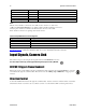
Output Signals, Camera Link
These signals indicate when data is valid, allowing you to clock the data from the camera to your
acquisition system. These signals are part of the Camera Link configuration and you should refer to the
Teledyne DALSA Camera Link Implementation Road Map for the standard location of these signals,
available from the Knowledge Center on our Web site:
(http:/ / www.teledynedalsa.com/ mv/ knowledge/ appnotes.aspx).
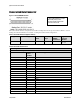
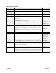
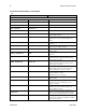
Clocking Signal
Indicates
LVAL (high)
Outputting valid line
DVAL (high)
Valid data (unused, tied high)
STROBE (rising edge)
Valid data
FVAL (high)
Outputting valid frame (unused, tied high)
The camera internally d igitizes 12 bits and ou tpu ts the 8 MSB or all 12 bits d ep end ing on the camera’s
Camera Link operating mode.
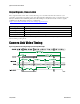
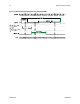
Camera Link Video Timing
Figure 12: Spyder3 Overview Timing Showing Input and Output Relationships