
User`s manual

22 Spyder3 S3-14 and S3-24 User's Manual
03-032-20117-00 Teledyne DALSA
11
16
CC3-
24
3
CC3+
12
15
CC4+
25
2
CC4-
13
13
inner shield
26
26
inner shield
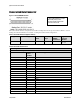
Notes:
*Exterior Overshield is connected to the shells of the connectors on both ends.
**3M part 14X26-SZLB-XXX-0LC is a complete cable assembly, including connectors.
Unused pairs should be terminated in 100 ohms at both ends of the cable.
Inner shield is connected to signal ground inside camera
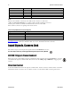
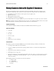
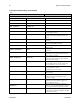
Table 9: Teledyne DALSA Camera Control Configuration
Signal
Configuration
CC1
EXSYNC
CC2
PRIN
CC3
Direction
CC4
Spare
See Appendix B for the complete Teledyne DALSA Camera Link configuration table, and refer to the
Knowledge Center on Teledyne DALSA’s Web site, for the official Camera Link documents.
Input Signals, Camera Link
The camera accepts control inputs through the Camera Link MDR26F connector.
The camera ships in internal sync, internal programmed integration (exposure mode 7) TDI Mode.
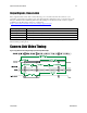
EXSYNC (Triggers Frame Readout)
Frame rate can be set internally using the serial interface. The external control signal EXSYNC is optional
and enabled through the serial interface. This camera uses the falling edge of EXSYNC to trigger pixel
readout.
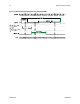
Direction Control
Control the CCD shift direction through the serial interface. Use the software command scd to determine
whether the direction control is set via software control or via the Camera Link control signal on CC3.
i