
User`s manual

Spyder3 S3-14 and S3-24 User's Manual 21
Teledyne DALSA 03-032-20117-00
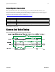
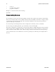
Camera Link Data Connector
Figure 11: Camera Link MDR26 Connector
The Camera Link interface is implemented as Base Configuration in the Spyder3 cameras. Refer to section
Setting the Camera Link Mode for details on setting the Camera Link configuration.
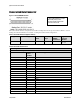
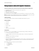
Table 7: Camera Link Hardware Configuration Summary
Configuration
8 Bit Ports Supported
Serializer Bit
Width
Number of
Chips
Number of
MDR26
Connectors
Applicable
Camera
Models
Base
A, B, C
28
1
1
The various
models
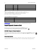
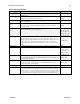
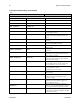
Table 8: Camera Link Connector Pin out
Base Configuration
One Channel Link Chip + Camera Control + Serial Communication
Camera Connector
Right Angle
Frame
Grabber
Channel Link Signal
1
1
inner shield
14
14
inner shield
2
25
X0-
15
12
X0+
3
24
X1-
16
11
X1+
4
23
X2-
17
10
X2+
5
22
Xclk-
18
9
Xclk+
6
21
X3-
19
8
X3+
7
20
SerTC+
20
7
SerTC-
8
19
SerTFG-
21
6
SerTFG+
9
18
CC1-
22
5
CC1+
10
17
CC2+
23
4
CC2-
**3M part 14X26-SZLB-XXX-0LC is a complete
cable assembly, including connectors.
Unused pairs should be terminated in 100
ohms at both ends of the cable.