Spyder3 S3-14 and S3-24 Camera Link Dual Line Scan Mono Camera User’s Manual Feb 23 2012 03-032-20117-00 www.teledynedalsa.
Spyder3 S3-14 and S3-24 User's Manual © 2012 Teled yne DALSA. All inform ation provid ed in this m anual is believed to be accurate and reliable. N o responsibility is assum ed by Teled yne DALSA for its use. Teled yne DALSA reserves the right to m ake changes to this inform ation w ithout notice. Reprod uction of this m anual in w hole or in part, by any m eans, is prohibited w ithout prior perm ission h aving been obtained from Teled yne DALSA. About Teledyne Technologies and Teledyne DALSA, Inc.
Spyder3 S3-14 and S3-24 User's Manual 3 Contents SYSTEM PRECAUTIONS AND CLEANING .................................................................................................................................. 5 THE SPYDER3 S3-14 AND S3-24 CAMERAS.............................................................................................................................. 7 CAMERA HIGHLIGHTS ..................................................................................................................
Spyder3 S3-14 and S3-24 User's Manual APPENDIX C .......................................................................................................................................................................... 92 EMC DECLARATION OF CONFORMITY .......................................................................................................................................................................................92 REVISION HISTORY ...................................................
Spyder3 S3-14 and S3-24 User's Manual 5 System Precautions and Cleaning Precautions Read these p recau tions and this m anu al carefu lly before u sing the cam era. Confirm that the cam era’s p ackaging is u nd am aged before op ening it. If the p ackaging is d am aged p lease contact the related logistics p ersonnel. Do not op en the hou sing of the cam era. The w arranty is void ed if the hou sing is op ened . Keep the cam era hou sing tem p eratu re in a range of 0 °C to 65 °C d u ring op eration.
Spyder3 S3-14 and S3-24 User's Manual tou ching the sensor. Scratches d iffract incid ent illu m ination. When exp osed to u niform illu m ination, a sensor w ith a scratched w ind ow w ill norm ally have brighter p ixels ad jacent to d arker p ixels. The location of these p ixels w ill change w ith the angle of illu m ination. Cleaning the Sensor Window Recommended Equipment Glass cleaning station w ith m icroscop e w ithin clean room . 3M ionized air gu n 980 (http :/ / solu tions.3m canad a.
Spyder3 S3-14 and S3-24 User's Manual 7 The Spyder3 S3-14 and S3-24 Cameras Camera Highlights The Sp yd er3 CL su rp asses its p red ecessor, the Sp yd er2, w ith 3x m ore resp onsivity a nd 2x the sp eed . At its core is d u al line scan technology that achieves u np reced ented resp onsivity and throu ghp u t rates of 80 m egap ixels p er second , w ithou t im p acting noise.
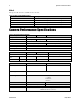
Spyder3 S3-14 and S3-24 User's Manual Models The Sp yd er3 CL cam era is available in these m od els. Table 1: Spyder3 CL Camera Models Overview Model Number Description S3-24-01K40-00-R 1k resolution, 2 sensor taps. Base Cam era Link configuration . S3-24-02K40-00-R 2k resolution, 2 sensor taps. Base Cam era Link configuration . S3-14-01K40-00-R 1k resolution, 1 sensor tap . Base Cam era Link configuration . S3-14-02K40-00-R 2k resolution, 1 sensor tap . Base Cam era Link configuration .
Spyder3 S3-14 and S3-24 User's Manual 9 Electrical Interface 1k and 2k Input Voltage 4k + 12 to +15 Volts DC Pow er Dissipation < 5 W (1k and 2k) Operating Tem perature < 7 W (4k) 0 ºC to 65 ºC Bit Wid th 8 or 12 bits user selectable Output Data Configuration Base Cam era Link *Lens m ount ad apters are available. Contact Teled yne DALSA Sales for m ore inform ation.
Spyder3 S3-14 and S3-24 User's Manual Test conditions unless otherwise noted 12-bit valu es, Flat Field Correction (FFC) enabled . CCD Pixel Rate: 40 m egap ixels/ second p er sensor tap . Line Rate: 5000 H z. N om inal Gain setting u nless otherw ise sp ecified . Light Sou rce: Broad band Qu artz H alogen, 3250k, w ith 750 nm high p ass filter installed . Am bient test tem p eratu re 25 °C. Unless sp ecified , all valu es are referenced at 12 bit. Exp osu re m od e d isabled .
Spyder3 S3-14 and S3-24 User's Manual 11 Figure 1: Spyder3 CL 1k and 2k Responsivity Spectral Responsivity.
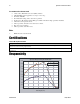
Spyder3 S3-14 and S3-24 User's Manual Derating Curves Figure 3: 1k and 2k Derating Curves 03-032-20117-00 Teledyne DALSA
Spyder3 S3-14 and S3-24 User's Manual 13 Figure 4: 4k Derating Curves Changes in DC offset with Integration Time (12bit, 0dB, HSM, 4K model) 4K model: Change in DC Offset vs Temperature (12bit, Integration Time 200us) 200.000 140 180.000 120 160.000 100 140.000 DN DN 80 120.000 +10dB HSM 100.000 +10dB LSM 60 80.000 40 60.000 -10dB LSM 40.000 20 20.000 0.000 0 3.3 2.0 1.0 0.5 0.3 0.2 0.1 0C 0.
Spyder3 S3-14 and S3-24 User's Manual Mechanicals Figure 5: 1k and 2k Mechanical Dimensions 03-032-20117-00 Teledyne DALSA
Spyder3 S3-14 and S3-24 User's Manual 15 Figure 6: 4k Mechanical Dimensions Mounting H eat generated by the cam era m u st be allow ed to m ove aw ay from the cam era. Mou nt the cam era on the front p late (u sing the p rovid ed m ou nting holes) w ith m axim u m contact to the area for best heat d issip ation.
Spyder3 S3-14 and S3-24 User's Manual Image Sensor The cam era u ses Teled yne DALSA’s d u al line scan sensor. The cam era can be configu red to read ou t in either high or low sensitivity m od e, tall p ixel m od e, and either forw ard or reverse shift d irection.
Spyder3 S3-14 and S3-24 User's Manual 17 Software and Hardware Setup Host System Requirements To achieve best system p erform ance, the follow ing m inim u m requ irem ents are recom m end ed : Base Cam era Link fram e grabber. Op erating system : Wind ow s XP Professional, Wind ow s Vista, Wind ow s 7 (either 32-bit or 64-bit for all) are su p p orted . Setup Steps: Overview Take the follow ing step s in ord er to setu p and ru n you r cam era system .
Spyder3 S3-14 and S3-24 User's Manual Step 1. Install and configure the frame grabber and graphics card Install Frame Grabber Install a Base Cam era Link fram e grabber accord ing to the m anu factu rer’s d escrip tio n. A list of fram e grabbers recom m end ed by Teled yne DALSA and su p p orting the Sp yd er3 cam eras is available on the Teled yne DALSA Web site here: w w w .teled yned alsa.com / m v/ p rod u cts/ fram egrabbers.
Spyder3 S3-14 and S3-24 User's Manual 19 Figure 10: Hirose 6-pin Circular Male—Power Connector Power Connector WARN IN G: It is extrem ely im p ortant that you ap p ly the ap p rop riate voltages to you r cam era. Incorrect voltages m ay d am age the cam era. Inp u t voltage requ irem ent: +12 V to +15 V DC. ! The cam era requ ires a single 6-p in H irose connector w ith a single voltage inp u t +12 VDC to +15 VDC for p ow er.
Spyder3 S3-14 and S3-24 User's Manual Status LED The cam era is equ ip p ed w ith a red / green LED u sed to d isp lay the statu s of the cam era's op er ation. The table below su m m arizes the op erating states of the cam era and the corresp ond ing LED states. When m ore than one cond ition is active, the LED ind icates the cond ition w ith the highest p riority. Error and w arning states are accom p anied by corresp ond ing m essages that fu rther d escribe the cu rrent cam era statu s.
Spyder3 S3-14 and S3-24 User's Manual 21 Camera Link Data Connector Figure 11: Camera Link MDR26 Connector **3M part 14X26-SZLB-XXX-0LC is a complete cable assembly, including connectors. Unused pairs should be terminated in 100 ohms at both ends of the cable. The Cam era Link interface is im p lem en ted as Base Configu ration in the Sp yd er3 cam eras. Refer to section Setting the Cam era Link Mod e for d etails on setting the Cam era Link configu ration.
Spyder3 S3-14 and S3-24 User's Manual 11 16 CC3- 24 3 CC3+ 12 15 CC4+ 25 2 CC4- 13 13 inner shield 26 26 inner shield Notes: *Exterior Overshield is connected to the shells of the connectors on both end s. **3M p art 14X26-SZLB-XXX-0LC is a com p lete cable assem bly, inclu d ing connectors. Unu sed p airs shou ld be term inated in 100 ohm s at both end s of the cable.
Spyder3 S3-14 and S3-24 User's Manual 23 Output Signals, Camera Link These signals ind icate w hen d ata is valid , allow ing you to clock the d ata from the cam era to you r acqu isition system . These signals are p art of the Cam era Link configu ration and you shou ld refer to the Teled yne DALSA Cam era Link Im p lem entation Road Map for the stand ard location of these signals, available from the Know led ge Center on ou r Web site: (http :/ / w w w .teled yned alsa.
Spyder3 S3-14 and S3-24 User's Manual Figure 13: Spyder3 Fixed (Programmed) Integration Timing with External EXSYNC 03-032-20117-00 Teledyne DALSA
Spyder3 S3-14 and S3-24 User's Manual Table 10: Spyder3 Input and Output Symbol Definition 25 Min (ns) tw SYN C The m inim um low w id th of the EXSYN C pulse w hen not in SMART EXSYN C m od e. 100 tw SYN C (SMART)* The m inim um low w id th of the EXSYN C pulse w hen in SMART EXSYN C m od es to guarantee the photosites are reset.
Spyder3 S3-14 and S3-24 User's Manual Step 3. Establish Communication with the Camera Power on the camera Tu rn on the cam era’s p ow er su p p ly. You m ay have to w ait u p to 60 second s w hile the cam era w arm s u p and p rep ares itself for op eration. Connect to the camera In ord er for you to com m u nicate w ith the cam era, a serial connection in the Cam era Link cable need s to be established .
Spyder3 S3-14 and S3-24 User's Manual 27 Using Camera Link with Spyder3 Cameras All of the cam era featu res can be controlled throu gh the serial interface. The cam era can also be u sed w ithou t the serial interface after it has been set u p correctly. For exam p le, fu nctions available inclu d e: Controlling basic cam era fu nctions su ch as gain and sync signal sou rce . Flat field correction. Mirroring and read ou t control Generating a test p attern for d ebu gging.
• • • Spyder3 S3-14 and S3-24 User's Manual t = tap id x = p ixel colu m n nu m ber y = p ixel row nu m ber Exam p le: to retu rn the cu rrent cam era settings gcp Camera Help Screen For qu ick help , the cam era can retu rn all available com m and s and p aram eters throu gh the serial interface. There are tw o d ifferent help screens available. One lists all of the available com m and s to configu re cam era op eration.
Spyder3 S3-14 and S3-24 User's Manual 29 At this p oint you are read y to start op erating the cam era in ord er to acqu ire im ages, set cam era fu nctions, and save settings.
Spyder3 S3-14 and S3-24 User's Manual To read all current camera settings, use the command: gcp GCP Screen Description GENERAL CAMERA SETTINGS Camera Model No.: S3-x0-0xK40-00-R Cam era m od el num ber. Camera Serial No.: xxxxxxxxx Cam era serial num ber. Firmware Version: xx-xx-xxxxx-xx Firm w are d esign revision num ber. CCI Version: xxxxx.xx CCI version num ber. FPGA Version: xxx.xx FPGA revision num ber.
Spyder3 S3-14 and S3-24 User's Manual 31 FPN Coefficients: off States w hether FPN coefficients are on or off. Set w ith the epc com m and . Refer to section Analog and Digital Signal Processing Chain for d etails. PRNU Coefficients: off States w hether PRN U coefficients are on or off. Set w ith the epc com m and . Refer to section Analog and Digital Signal Processing Chain for d etails. Number of Line Samples: 1024 N um ber of lines sam ples set w ith the css com m and .
Spyder3 S3-14 and S3-24 User's Manual Saving and Restoring Settings Use these com m and s to select, load , and save factory , u ser, and coefficient sets. Camera Link Commands Parameter Description lpc i Load s your previously saved pixel coefficients from non -volatile m em ory to active status. 0: factory calibration. 1 – 4: user sets. rfs Restores the cam era’s factory settings. The FPN and PRN U coefficients are reset to 0.
Spyder3 S3-14 and S3-24 User's Manual 33 Factory Settings On first initialization, the cam era op erates u sing the factory settings. You can restore the original factory settings at any tim e u sing the com m and rfs. User Settings You can save or restore you r u ser settings to non -volatile m em ory u sing the follow ing com m and s. Pixel coefficients and LUTs are stored sep arately from other d ata. To save all cu rrent u ser settings to non -volatile m em ory, u se the com m and w u s.
Spyder3 S3-14 and S3-24 User's Manual Mode Configuration Command Models Taps Bit Depth clm 2 S3-24-01K40 2 8 S3-24-02K40 2 smm 0 = CL tap 1 (1-1024) CL tap 2 (1025-2048) smm 1 = CL tap 1 (2048-1025) CL tap 2 (1024-1) S3-24-04k-40 2 smm 0 = CL tap 1 (1-2048) CL tap 2 (2049-4096) smm 1 = CL tap 1 (4096-2049) CL tap 2 (2048-1) S3-24-01K40 2 S3-24-02K40 2 smm 0 = CL tap 1 (1-1024) CL tap 2 (1025-2048) smm 1 = CL tap 1 (2048-1025) CL tap 2 (1024-1) S3-24-04k-40 2 smm 0 = CL tap 1 (1-2048
Spyder3 S3-14 and S3-24 User's Manual 35 Setting the Pixel Readout Direction (Mirroring Mode) The smm com m and sets the tap read ou t from left to right or from right to left. This com m and is esp ecially u sefu l if the cam era m u st be m ou nted u p sid e d ow n. Camera Link Command Parameter Description sm m i Read out d irection. Allow able values are: 0 = All pixels are read out from left to right. 1 = All pixels are read out from right to left.
Spyder3 S3-14 and S3-24 User's Manual Table 12: Forward or Reverse Pixel Readout Camera model Readout direction Command Tap 1 Tap 2 S3-14-01k40 Left to Right smm 0 1-1024 n/ a Right to Left smm 1 1024-1 n/ a Left to Right smm 0 1-512 513-1024 Right to Left smm 1 1024-513 512-1 Left to Right smm 0 1-2048 n/ a Right to Left smm 1 2048-1 n/ a Left to Right smm 0 1-1024 1025-2048 Right to Left smm 1 2048-1025 1024-1 Left to Right smm 0 1-2048 2049-4096 Right to Lef
Spyder3 S3-14 and S3-24 User's Manual 37 Sensitivity Mode and Pixel Readout The cam era has the op tion to op erate in either high sensitivity (d u al line) or low sensitivity (single line) m od es, or in tall p ixel m od e. When in high sensitivity m od e, the cam era u ses both line scan sensors and its resp onsivity increases accord ingly. When in low sensitivity m od e, the cam era u ses the bottom sensor only.
Spyder3 S3-14 and S3-24 User's Manual Pixel Detail 28/20µm 14/10µm CCD Readout Shift Register Sensor 1 and 2 (28µm x 14µm OR 20µm x 10µm) CCD Readout Shift Register Sensor Shift Direction When in high sensitivity m od e, you can select either forw ard or reverse CCD shift d irection. This accom m od ates object d irection change on a w eb and allow s you to m ou nt the cam era ―u p sid e d ow n‖.
Spyder3 S3-14 and S3-24 User's Manual 39 Exposure Mode, Line Rate and Exposure Time Overview You have a choice of op erating in one of seven m od es. The cam era’s line rate (synchronization) can be generated internally throu gh the set sync frequ ency softw are com m and ssf or set externally w ith an EXSYN C signal, d ep end ing on you r m od e of op eration. To select how you w ant the cam era’s line rate to be generated : 1.
Spyder3 S3-14 and S3-24 User's Manual Exposure Modes in Detail Mode 2: Internally Programmable Line Rate and Exposure Time (Factory Setting) Mod e 2 op erates at a m axim u m line rate and exp osu re tim e. When setting the line rate (u sing the ssf com m and ), exp osu re tim e w ill be red u ced , if necessary, to accom m od ate the new line rate.
Spyder3 S3-14 and S3-24 User's Manual 41 Mode 4: Smart EXSYNC, External Line Rate and Exposure Time In this m od e, EXSYN C sets both the line p eriod and the exp osu re tim e. The rising ed ge of EXSYN C m arks the beginning of the exp osu re and the falling ed ge initiates read ou t. Example 3: Trigger Period is Repetitive and Greater than Read Out Time.
Spyder3 S3-14 and S3-24 User's Manual Mode 7: Internally Programmable Line Rate, Maximum Exposure Time In this m od e, the line rate is set internally w ith a m axim u m exp osu re tim e.
Spyder3 S3-14 and S3-24 User's Manual 43 Setting the Exposure Time Sets the cam era’s exp osu re tim e is µs. Cam era m u st be op erating in m od e 2, 6, or 8. Camera Link Command Parameter Description set f Desired exposure tim e in µs. Allow able range is 3 to 3300µs.* Notes To read the current line frequency, use the com m and gcp or get set. If you enter an invalid line rate frequency, an error m essage is returned . *The exposure tim e range is based on the current line rate.
Spyder3 S3-14 and S3-24 User's Manual Select Cable Sets the cable p aram eters. Camera Link Command Parameter Description scb i Output com pare value. Available values are: 0 to 255. Notes In m ed ium configuration, both cables m ust be the sam e length. Only one copy of this setting is saved in the cam era (rather than w ith each setting). On the lfs (load factory settings) com m and the cable length w ill be set to the factory d efault of 100.
Spyder3 S3-14 and S3-24 User's Manual 45 CCD Shift Direction When in high sensitivity m od e, selects the forw ard or reverse CCD shift d irection, internally or externally controlled . This accom m od ates object d irection change on a w eb and allow s you to m ou nt the cam era ―u p sid e d ow n‖. Camera Link Command Parameter Description scd i Shift d irection. Allow able values are: 0 = Internally controlled , forw ard CCD shift d irection. 1 = Internally controlled , reverse CCD shift d irection.
Spyder3 S3-14 and S3-24 User's Manual Setting the Mirror Mode Sets the cam era’s m irror m od e. Set the p ixel read ou t as either left to right, or right to left. Camera Link Command Parameter Description sm m i 0: Pixels read out left to right. 1: Pixels read out right to left.
Spyder3 S3-14 and S3-24 User's Manual 47 Data Processing Setting a Region of Interest (ROI) Sets the pixel range used to collect the end -of-line statistics and sets the region of pixels used in the ccg, gl, gla, ccf, and ccp com m and s. In m ost ap p lications, the field of view exceed s the requ ired object size and these extraneou s areas shou ld be ignored .
Spyder3 S3-14 and S3-24 User's Manual Analog and Digital Signal Processing Chain Processing Chain Overview and Description The follow ing d iagram show s a sim p lified block d iagram of the cam era’s analog and d igital p rocessing chain. The analog p rocessing chain begins w ith an analog gain ad ju stm ent, follow ed by an analog offset ad ju stm ent. These ad ju stm ents are ap p lied to the vid eo analog signal p rior to its d igitization by an A/ D converter.
Spyder3 S3-14 and S3-24 User's Manual 49 Digital Processing To op tim ize cam era p erform ance, d igital signal p rocessing shou ld be com p leted after any analog ad ju stm ents. 1. Fixed p attern noise (FPN ) calibration (calcu lated u sing the ccf com m and ) is u sed to su btract aw ay ind ivid u al p ixel d ark cu rrent. 2.
Spyder3 S3-14 and S3-24 User's Manual Calibrating Camera Gain Instead of m anu ally setting the analog gain to a sp ecific valu e, the cam era can d eterm ine ap p rop riate gain valu es. This com m and calcu lates and sets the analog gain accord ing to the algorithm d eterm ined by the first p aram eter. Camera Link Command Parameter Description ccg i t i i Calibration algorithm to use.
Spyder3 S3-14 and S3-24 User's Manual 51 Example sao 2 35 Calibrating the Camera to Remove Non-Uniformity (Flat Field Correction) Flat Field Correction Overview This cam era has the ability to calcu late correction coefficients in ord er to rem ove non -u niform ity in the im age. This vid eo correction op erates on a p ixel-by-p ixel basis and im p lem ents a tw o-p oint correction for each p ixel.
Spyder3 S3-14 and S3-24 User's Manual Flat Field Correction Restrictions It is im p ortant to d o the FPN correction first. Resu lts of the FPN correction are u sed in the PRN U p roced u re. We recom m end that you rep eat the correction w hen a tem p eratu re change greater than 10°C occu rs or if you change the analog gain, integration tim e, or line rate. PRN U correction requ ires a clean, w hite reference. The qu ality of this reference is im p ortant for p rop er calibration.
Spyder3 S3-14 and S3-24 User's Manual 53 Calibration Overview When a cam era im ages a u niform ly lit field , id eally, all of the p ixels w ill have the sam e gray valu e. H ow ever, in p ractice, this is rarely the case (see exam p le below ) as a nu m ber of factors can contribu te to gray scale non-u niform ity in an im age: Lighting non -u niform ities and lens d istortion, PRN U (p ixel resp onse non-u niform ity) in the im ager, FPN (fixed p attern noise) in the im ager, etc. Figure 27.
Spyder3 S3-14 and S3-24 User's Manual 2. Ad ju st the line rate so that the average ou tpu t is abou t 80% of the fu ll ou tpu t, or below the PRN U target valu e by: Ad ju sting the lighting, if you are u sing an internal exposu re m od e. Or, Ad ju sting the line rate, if you are u sing the Sm art Exsync m od e. 3.
Spyder3 S3-14 and S3-24 User's Manual 55 Setting a Pixel’s FPN Coefficient Sets an ind ivid u al p ixel’s FPN coefficient. Camera Link Command Parameter Description sfc x i Notes x The pixel num ber from 1 to sensor pixel count i Coefficient value in a range from 0 to 2047 (12 bit LSB). Example sfc 10 50 Setting Digital Offset Sets the d igital offset. Digital offset is set to zero w hen you p erform FPN correction (ccf com m and ).
Spyder3 S3-14 and S3-24 User's Manual PRNU Correction Perform s PRN U calibration to user entered value and elim inates the d ifference in responsivity betw een the m ost and least sensitive pixel, creating a uniform response to light. Using this com m and , you m ust provid e a calibration target. Execu ting these algorithm s cau ses the ssb com m and to be set to 0 (no backgrou nd su btraction) and the ssg com m and to 4096 (u nity d igital gain).
Spyder3 S3-14 and S3-24 User's Manual 57 This algorithm is m ore robust and repeatable than algorithm 1 because it uses an average pixel value rather than a num ber above target. H ow ever, this algorithm is slow er. i: Peak target value in a range from 1024 to 4055DN . The target value m ust be greater than the current peak output value.
Spyder3 S3-14 and S3-24 User's Manual Example spc 1024 10000 Subtracting Background Use the backgrou nd su btract com m and after p erform ing flat field correction if you w ant to im p rove you r im age in a low contrast scene. It is u sefu l for sy stem s that p rocess 8 bit d ata bu t w ant to take ad vantage of the cam era’s 12 bit d igital p rocessing chain. You shou ld try to m ake you r d arkest p ixel in the scene equ al to zero.
Spyder3 S3-14 and S3-24 User's Manual 59 Returning Calibration Results and Errors Returning All Pixel Coefficients Retu rns all the cu rrent p ixel coefficients in the ord er FPN , PRN U, FPN , PRN U… for the range sp ecified by x1 and x2. The cam era also retu rns the p ixel nu m ber w ith every fifth coefficient. Camera Link Command Parameter Description d pc x1 x2 x1: Start pixel to d isplay in a range from 1 to sensor pixel count. x2 End pixel to d isplay in a range from x1 to sensor pixel count.
Spyder3 S3-14 and S3-24 User's Manual Enabling and Disabling Pixel Coefficients Enables and d isables FPN and PRN U coefficients Camera Link Command Parameter Description epc i i Notes i FPN coefficients. 0 = FPN coefficients d isabled 1 = FPN coefficients enabled i PRN U coefficients.
Spyder3 S3-14 and S3-24 User's Manual Location Value 7 Line sum (23…16) 8 Line sum (31…24) 9 Pixels above threshold (7…0) 10 Pixels above threshold (15…8) 11 Pixels below threshold (7…0) 12 Pixels below threshold (15…8) 13 Differential line sum (7..
Spyder3 S3-14 and S3-24 User's Manual Look-Up Tables N ote: This inform ation only ap p lies to the 4k m od el cam era. The flat field corrections FPN and PRN U assu m e a linear resp onse to the am ou nt of light by the sensor, ou tp u t nod e, analog am p lifier, and analog to d igital converter. To correct any non -linearity in this system of com p onents a Look-Up Table (LUT) has been im p lem ented in the FPGA for each tap im m ed iately after the ADC.
Spyder3 S3-14 and S3-24 User's Manual 63 Write Input LUT Saves cu rrent valu es of inp u t LUT that are in FPGA SDRAM to Flash m em ory or a PC file. Camera Link Command Parameter Description wil 0 = Factory set 1 to 4 = User sets Notes LUT u se is enabled or d isabled w ith the EIL com m and . Set 0 can only be w ritten from factory m od e. Example Saving and Restoring PRNU and FPN Coefficients Saving the Current PRNU Coefficients The w pc com m and saves the cu rrent PRN U coefficients.
Spyder3 S3-14 and S3-24 User's Manual 4 = Coefficient set fou r Example w fc 2 Loading a Saved Set of Coefficients The lpc com m and Load s one of the 4 saved sets of p ixel coefficients. In ad d ition, a factory calibrated set of coefficients is available. Camera Link Command Parameter Description lp c i Notes FPN coefficients set to save. 0 = Factory calibrated p ixel coefficients.
Spyder3 S3-14 and S3-24 User's Manual 65 Diagnostics Generating a Test Pattern Use the svm com m and to generate a test p attern to aid in system d ebu gging. The test p atterns are u sefu l for verifying cam era tim ing and connections. The follow ing tables show each available test p attern. Camera Link Command Parameter Description svm 0 Vid eo. svm sm m 1 0 12 bit test pattern.
Spyder3 S3-14 and S3-24 User's Manual svm sm m 2 1 svm sm m 1 0 svm sm m 1 1 svm sm m 2 1 03-032-20117-00 12 bit test pattern 1 tap m od el: 8 bit test pattern t tap m od el: Teledyne DALSA
Spyder3 S3-14 and S3-24 User's Manual 67 Returning Video Information The cam era’s m icrocontroller has the ability to read vid eo d ata. This fu nctionality can be u sed to verify cam era op eration and to p erform basic testing w ithou t having to conn ect the cam era to a fram e grabber. This inform ation can also be u sed to collect line statistics for calibrating the cam era.
Spyder3 S3-14 and S3-24 User's Manual Returning Averaged Lines of Video Setting the Number of Lines to Sample The css com m and sets the nu m ber of lines to sam p le w hen u sing the gla com m and or w hen p erform ing an FPN or PRN U calibration. Camera Link Command Parameter Description css m N um ber of lines to sam ple. Allow able values are 256, 512, or 1024 (factory setting). Notes To retu rn the cu rrent setting, u se the gcp com m and or get css.
Spyder3 S3-14 and S3-24 User's Manual 69 Voltage Measurement The com m and vv d isp lays the cam era’s inp u t voltage. N ote that the voltage m easu rem ent featu re of the cam era p rovid es only ap p roxim ate resu lts (typ ically w ithin 10%). The m easu rem ent shou ld not be u sed to set the ap p lied voltage to the cam era bu t only u sed as a test to isolate gross p roblem s w ith the su p p ly voltage.
Spyder3 S3-14 and S3-24 User's Manual Returning Camera Settings with Get Commands You can also retu rn ind ivid u al cam era settings by inserting a ― get” in front of the com m and that you w ant to qu ery. If the com m and has a tap or p ixel nu m ber p aram eter, you m u st also insert the tap nu m ber or p ixel nu m ber that you w ant to qu ery. To view a help screen listing the follow ing get com m and s, u se the com m and gh.
Spyder3 S3-14 and S3-24 User's Manual 71 Mnemonic Syntax Parameters Description Cam era Link m od e clm i m Sets the cam era’s bit w id th w here: For S3-1x-01K40 and S3-1x-02K40 0 = 8 bits, 1 tap 1 = 12 bits, 1 tap For S3-2x-01K40 and S3-2x-02K40 2 = 8 bits, 2 taps 3 = 12 bits, 2 taps calculate PRN U algorithm cpa i i Perform s PRN U calibration accord ing to the selected algorithm .
Spyder3 S3-14 and S3-24 User's Manual Mnemonic Syntax Parameters Description enable (EXSYN C) jitter ejt i 0 – 1. This feature w ill prevent line-to-line output variations d ue to EXYN C jitter at the m axim um line rate. end of line sequence els i Sets the end -of-line sequence: 0: Off 1: On enable noise correction enc i 0 – 1. Enables FIR filter in the output. The first tw o pixels are not filtered .
Spyder3 S3-14 and S3-24 User's Manual 73 Mnemonic Syntax Parameters Description get signal frequency gsf i Read s the requested Cam era Link control frequency. 1 = EXSYN C frequency 2 = Spare 3 = Direction get status led gsl Returns the current state of the cam era’s LED w here: 1 = Red 2 = Green 5 = Blinking green 6 = Blinking red help h Display the online help. Refer to the Select Cable Cam era ASCII Com m and H elp for d etails.
Spyder3 S3-14 and S3-24 User's Manual Mnemonic Syntax Parameters Description set cable param eter scb i Set the cable param eter. Output com pare value. Available values are: 0-255. set ccd d irection scd i Sets the CCD shift d irection w here: 0 = Forw ard CCD shift d irection. 1 = Reverse CCD shift d irection. 2 = Externally controlled d irection control via CC3. (CC3=1 forw ard , CC3=0 reverse.
Spyder3 S3-14 and S3-24 User's Manual 75 Mnemonic Syntax Parameters Description set subtract background ssb t i Subtract the input value from the output signal. t = Tap value. 0 for all taps or 1 to number of camera taps for ind ivid ual tap selection. i = Subtracted value in a range from 0 to 4095. set sync frequency ssf i Set the fram e rate to a value from 300H z to 36000H z (2k m od el) or 300H z to 68000H z (1k m od el). Value round ed up/ d ow n as required .
Spyder3 S3-14 and S3-24 User's Manual Error Handling The follow ing table lists w arning and error m essages and p rovid es a d escrip tion and p ossible cau se. Warning m essages are retu rned w hen the cam era cannot m eet the fu ll valu e of the requ est; error m essages are retu rned w hen the cam era is u nable to com p lete the requ est.
Spyder3 S3-14 and S3-24 User's Manual 77 Clearing Dark Current Gate Dark Current Clear N ote: This featu re is not available for the S3-24-04k40 cam era m od el. Im age sensors accu m u late d ark cu rrent w hile they w ait for a trigger signal. If the read ou t is not triggered in a reasonable am ou nt of tim e, then this d ark cu rrent accu m u lation m ay increase to an excessive am ou nt.
S3-24-04k40 Spyder3 S3-14 and S3-24 User's Manual 4.4KH z 7.24KH z Immediate read out mode (default, srm 2) In this m od e the im age is read ou t, inclu d ing accu m u lated d ark cu rrent, im m ed iately follow ing the trigger or the EXSYN C falling ed ge. There are no line rate lim itations other than the am ou nt of gate d ark cu rrent that can be tolerated at low line rates. There are no tim ing or exp osu re anom alies other than situ ations w here EXSYN C is rem oved from cam era.
Spyder3 S3-14 and S3-24 User's Manual 79 Auto Mode (srm 0) N ote: This featu re is not available for the S3-24-04k40 cam era m od el. In this m od e the line rate from the cam era w ill au tom atically cau se a sw itch betw een the gate d ark cu rrent clear m od e and non gate d ark cu rrent clear m od e. The frequ ency of w hen this m od e sw itchover occu rs d ep end s on the cam era m od el.
Spyder3 S3-14 and S3-24 User's Manual SRM 0, Auto Mode. Time Period Operating Region Refer to Figure 28. Operating Mode T0 Dark Current Dum p state T1 Im m ed iate Read out state SRM 0, Auto Mode. Time Period Operating Region Refer to Figure 28. Operating Mode T0 Im m ed iate Read out state T1 Dark Current Dum p state T2 Im m ed iate Read out state SRM 2, Immediate Readout Mode. Operating Region Time Period Refer to Figure 28.
Spyder3 S3-14 and S3-24 User's Manual 81 Dark Cu rrent Du m p to Im m ed iate Read ou t (T IN T > #) F DUMP F IMMEDIATE EXSYNC T DUMP T INT T VERT_TRANS LVAL Valid Dark Cu rrent Du m p to Im m ed iate Read ou t: Mu lti-Line Artifacts SRM 0, Auto Mode. Time Period Operating Region Refer to Figure 28. Operating Mode T0 Dark Current Dum p state T1 Im m ed iate Read out state SRM 0, Auto Mode. Time Period Operating Region Refer to Figure 28.
Spyder3 S3-14 and S3-24 User's Manual Dark Cu rrent Du m p to Im m ed iate Read ou t (T IN T < #) F DUMP >F DUMP (MAX) EXSYNC T DUMP T INT T VERT_TRANS LVAL Valid Dark Cu rrent Du m p to Im m ed iate Read ou t (T IN T > #) F DUMP >F DUMP (MAX) EXSYNC T DUMP T INT T VERT_TRANS LVAL Valid Im m ed iate Read ou t to Dark Cu rrent Du m p : H ysteresis Artifacts SRM 0, Auto Mode. Time Period Operating Region Refer to Figure 28.
Spyder3 S3-14 and S3-24 User's Manual 83 F IMMEDIATE F DUMP EXSYNC T DUMP T INT T VERT_TRANS LVAL Valid Teledyne DALSA 03-032-20117-00
Spyder3 S3-14 and S3-24 User's Manual Setting the Readout Mode Use this com m and to clear ou t d ark cu rrent charge in the vertical transfer gates im m ed iately before the sensor is read ou t. Camera Link Command Parameter Description srm 0: Auto. Clears d ark current below ~ 45% of the m axim um line rate. (1k and 2k cam era m od els only.) Notes Mod es 0 and 1 are n ot available to the 4k cam era m od el. The vertical transfer gates collect d ark current d uring the line period .
Spyder3 S3-14 and S3-24 User's Manual 85 Appendix B Camera Link Reference, Timing, and Configuration Table Cam era Link is a com m u nication interface for vision ap p lications. It p rovid es a connectivity stand ard betw een cam eras and fram e grabbers. A stand ard cable connection w ill red u ce m anu factu rers’ su p p ort tim e and greatly red u ce the level of com p lexity and tim e need ed for cu stom ers to su ccessfu lly integrate high sp eed cam eras w ith fram e grabbers.
Spyder3 S3-14 and S3-24 User's Manual • Sp are— A sp are has been d efined for fu tu re u se. All fou r enable signals m u st be p rovid ed by the cam era on each Channel Link chip . All u nu sed d ata bits m u st be tied to a know n valu e by the cam era. For m ore inform ation on im age d ata bit allocations, refer to the official Cam era Link sp ecification located in the Know led ge Center on Teled yne DALSA’s w ebsite.
Spyder3 S3-14 and S3-24 User's Manual 87 Camera Link Bit Definitions BASE Configuration Mode T0 Port A Bits 0 thru 7 Port B Bits 0 thru 7 Port C Bits 0 thru 7 Mod e 0 1 Tap 8 bit Tap 1 LSB..Bit 7 xxxxxxx xxxxxxx Mod e 1 1 Tap n bit Where n=10,12 Tap 1 LSB..Bit 7 Tap 1 Bits 8,9,10,11, xxxxxxx Mod e 2 2 Tap 8 bit Mod e 3 2 Tap n bit Where n=10,12 Tap 1 LSB..Bit 7 Tap 2 LSB..Bit7 xxxxxxx Tap 1 LSB..Bit 7 Tap 1 Bits 8,9,10,11, Tap 2 Bits 8,9,10,11 Tap 2 LSB..
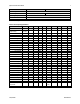
Spyder3 S3-14 and S3-24 User's Manual Camera Interface Parameters (PRELIMINARY) Table 21: Frame Grabber Interface Parameters Item (when S3-14-01k40 programmable configuration the options are separated with a | ) S3-24-01k40 S3-14-02k40 S3-24-02k40 S3-24-04k-40 1 1 1 1 1 Im ager Colum ns 1024 1024 2048 2048 4096 Im ager Row s Line Scan/ TDI are d efined as 1 1 1 1 1 1 N um ber of CCD Taps <1,2,3…..
Spyder3 S3-14 and S3-24 User's Manual 89 Item (when programmable configuration the options are separated with a | ) S3-14-01k40 S3-24-01k40 S3-14-02k40 S3-24-02k40 Configuration Definition Cx= H DW, N um ber of Output Taps, Bit Wid th, N um ber of Processing N od es w here Cx is the configuration ID x is <1,2,3…> H DW is N um ber of Output Taps is <1,2,3…> Bit w id th is <8, 10, 12…> N um ber Processing N od es is <1 or 2> C1 = Base, 1, 8, 1 C2 = Base, 1, 12, 1 C1 = Base, 2,
Spyder3 S3-14 and S3-24 User's Manual Item (when programmable configuration the options are separated with a | ) S3-14-01k40 S3-24-01k40 S3-14-02k40 S3-24-02k40 S3-24-04k-40 RGB Pattern Size < (T1, Colum ns*Row s) (T2, Colum ns*Row s) (T3, Colum ns*Row s….
Spyder3 S3-14 and S3-24 User's Manual 91 Item (when programmable configuration the options are separated with a | ) S3-14-01k40 S3-24-01k40 S3-14-02k40 S3-24-02k40 S3-24-04k-40 CC3 Forw ard / Reverse Forw ard / Reverse Forw ard / Reverse Forw ard / Reverse Forw ard / Reverse CC4 Spare Spare Spare Spare Spare DVAL out Strobe Valid Strobe Valid Strobe Valid Strobe Valid Strobe Valid Spare out (For future use) Spare Spa
Spyder3 S3-14 and S3-24 User's Manual Appendix C EMC Declaration of Conformity We, Teledyne D ALSA 605 McMurray Rd.
Spyder3 S3-14 and S3-24 User's Manual 93 Revision History Number Description Date 00 Prelim inary release.
Spyder3 S3-14 and S3-24 User's Manual Index A E analog processing, 47 applications, 6 EIA-644 Reference, 84 electrical specs, 8 EMC Com pliance Stand ard s, 9 EMC Declaration of Conform ity, 91 error m essages, 75 exposure m od e overview, 38 setting, 38 timing, 39 EXSYN C, 21 external trigger, 21 C calibrating the cam era, 50, 53, 56 cam era control configuration, 85 messages, 75 cam era control signals, 21, 85 Cam era Link configurations, 20, 32 connector, 20 mode, 33, 44 outputs, 22 signals, 85 c
Spyder3 S3-14 and S3-24 User's Manual 95 L LED, 19 line statistics, 66 LVAL, 22, 84 LVDS, 84 pairs, 85 LVDS pairs, 85 system, 16 resolution, 7 restoring factory settings, 32 roi.