
User`s manual


48 Piranha HS 4x User’s Manual
03-32-10040-03 PRELIMINARY DALSA Corp.
image data bit allocations, refer to the official Camera Link specification on the
vfm.dalsa.com
Web site.
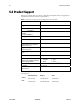
Camera Control Signals
Four LVDS pairs are reserved for general-purpose camera control. They are defined as
camera inputs and framegrabber outputs. Camera manufacturers can define these signals
to meet their needs for a particular product. DALSA has defines these signals
Table 11: Standard DALSA Naming Conventions
DALSA
Standard
Camera Link
Name
HS-41
Configuration
EXSYNC CC1 EXSYNC
PRIN CC2 SPARE
FORWARD CC3 SPARE
SPARE CC4 SPARE
Communication
Two LVDS pairs have been allocated for asynchronous serial communication to and from
the camera and framegrabber. Cameras and framegrabbers must support 9600 baud, as a
minimum requirement. These signals are
• SerTFG—Differential pair with serial communications to the framegrabber.
• SerTC—Differential pair with serial communications to the camera.
The serial interface will have the following characteristics: one start bit, one stop bit, no
parity, and no handshaking. It is recommended that framegrabber manufacturers supply
both a user interface and a software application programming interface (API) for using
the asynchronous serial communication port. The user interface will consist of a terminal
program with minimal capabilities of sending and receiving a character string and
sending a file of bytes. The software API will provide functions to enumerate boards and
send or receive a character string. See Appendix B in the Official Camera Link
specification on the vfm.dalsa.com
Web site.
Power
Power will not be provided on the Camera Link connector. The camera will receive power
through a separate cable. DALSA defines our own power connector, current, and voltage
requirements.