High Sensitivity Line Scan CCD Camera Piranha HS 4x-02K30 HS-40-02K30, HS-41-02K30 Camera User’s Manual 14-Oct-04 03-32-10040-03 www.dalsa.
Piranha HS 4x User’s Manual © 2004 DALSA. All information provided in this manual is believed to be accurate and reliable. No responsibility is assumed by DALSA for its use. DALSA reserves the right to make changes to this information without notice. Reproduction of this manual in whole or in part, by any means, is prohibited without prior permission having been obtained from DALSA.
Piranha HS 4x User’s Manual 3 Contents Introduction to the Piranha HS 4x High Sensitivity Line Scan Cameras ___________________ 5 1.1 Camera Highlights .......................................................................................................................................................5 1.2 Image Sensor ...............................................................................................................................................................7 1.
Piranha HS 4x User’s Manual 5.3 Specific Solutions .........................................................................................................................................................44 5.4 Product Support ...........................................................................................................................................................46 Camera Link™ Reference and Configuration Table ________________________________ 47 Camera Link™ Configuration Table ......
Piranha HS 4x User’s Manual 5 1 Introduction to the Piranha HS 4x High Sensitivity Line Scan Cameras 1.1 Camera Highlights DALSA Corp. 2 • Responsivity up to 1610 DN/(nJ/cm ) • 52 kHz line rates • 2048 pixels, 13µm x 13µm, 100% fill factor • 120MHz data rate.
Piranha HS 4x User’s Manual Description The Piranha HS 4x cameras offer incredible performance at a low cost. Because they use TDI technology, the Piranha HS 4x cameras are highly sensitive—50 times greater responsivity than standard line scan cameras.
Piranha HS 4x User’s Manual 7 1.2 Image Sensor The Piranha HS 4x cameras use DALSA’ s 2048 pixel, 4-output, stage selectable, unidirectional TDI IT-E4-2048B sensor. TDI Imaging Region 13µm x 13µm Pixels 64 TDI Rows, 2048 Columns 64 TDI 48 TDI TDI Col. 2 TDI Col.1 TDI Col. 2048 TDI Col. 2047 Figure 1. IT-E4-2048B Image Sensor 32 TDI 24 TDI 16 TDI 5 ISO Rows Tap 1 Pixels 512 to 1 Tap 2 Tap 3 Pixels Pixels 1024 to 513 1536 to 1025 Tap 4 Pixels 2048 to 1537 1.
Piranha HS 4x User’s Manual Optical Interface Feature / Specification Units Value Notes (F Mount) ° µm 46.5 ±0.18mm ±0.6 <100 over sensor Sensor Alignment z 0z Parallelism/Tilt Mechanical Interface Feature / Units Specification Value Notes Camera Size mm 85x85x50 Excluding lens and connectors Mass Kg 1.
Piranha HS 4x User’s Manual 9 Operating Ranges Value PRNU (pixel to pixel) without correction with correction Units Min Nom % of Output Saturation Output Amplitude DN Calibrated DC Offset DN Max Notes 10 2 @ 64 stages 248 ±2 3 5 Antiblooming 7 100x Regulatory EMI CISPR-22 EMC EN55024 Shock and Vibration MIL-STD-810E Test conditions unless otherwise noted: 1. Data Rate: 30 MHz 2. Line Rate: maximum 52 kHz ±10% (FPN and PRNU measured at minimum 1kHz line rate) 3.
03-32-10040-03 Piranha HS 4x User’s Manual PRELIMINARY DALSA Corp.
Piranha HS 4x User’s Manual 11 2 Camera Hardware Interface 2.1 Installation Overview When setting up your camera, you should take these steps: This installation overview assumes you have not installed any system components yet. 1. Power down all equipment. 2. Following the manufacturer’s instructions, install the framegrabber (if applicable). Be sure to observe all static precautions. 3. Install any necessary imaging software. 4. Before connecting power to the camera, test all power supplies.
Piranha HS 4x User’s Manual 2.2 Input/Output Connectors Figure 3: Piranha HS 4x Input/Output Connectors Camera Link™ Camera Link™ Diagnostic LED +12V to +15V and Ground 2.3 Connectors, Pinouts, and Cables The Piranha HS 4x cameras use: • Two high-density 26-pin MDR26 connectors for Camera Link control signals, data signals, and serial communications. See Figure 4: MDR26 Connector below. • A Hirose 6 pin power connector. See Figure 5: Hirose 6-pin Circular Male Power Connector on page 13.
Piranha HS 4x User’s Manual 13 Camera Link Cable Medium Configuration Up to an additional 2 Channel Link Chips Base Configuration One Channel Link Chip + Camera Control + Serial Communication Camera Right Angle Channel Connector Frame Link Signal Grabber Camera Connector Right AngleFrame Grabber Channel Cable Link Signal Name 4 23 Y2- PAIR3- 4 23 X2- 17 10 Y2+ PAIR3+ 17 10 X2+ 5 22 Yclk- PAIR4- 5 22 Xclk- 18 9 Yclk+ PAIR4+ 18 9 Xclk+ 6 21 Y3- PAIR5- 6 21 X3- 19 8
Piranha HS 4x User’s Manual Pin Description Pin Description 1 +12V to +15V 4 GND 2 +12V to +15V 5 GND 3 +12V to +15V 6 GND 2.4 Power Supplies The camera requires a single voltage input (+12 to +15V). The camera meets all performance specifications using standard switching power supplies, although wellregulated linear supplies provide optimum performance.
Piranha HS 4x User’s Manual 15 2.6 LED Status Indicators The camera is equipped with a red/green LED used to display the operational status of the camera. The following table summarizes the operating states of the camera and the corresponding LED states.
03-32-10040-03 Piranha HS 4x User’s Manual PRELIMINARY DALSA Corp.
Piranha HS 4x User’s Manual 17 3 Software Interface: How to Control the Camera i This chapter outlines the more commonly used commands. See Appendix B on page 51 for a list of all available commands. All camera features can be controlled through the serial interface. The camera can also be used without the serial interface after it has been set up correctly.
Piranha HS 4x User’s Manual Camera Initialization in progress, Please Wait ... OK> 5. Set up the framegrabber to receive the data. Following the framegrabber manufacturer’s instructions, set up the parameters described in the Camera Link™ Configuration Table on page 49. 6. Once the framegrabber is set up for data processing and the camera is powered up, run your image processing software. You should be able to see an image from the camera when exposed to a light source. 7.
Piranha HS 4x User’s Manual 19 3.3 Saving and Restoring Settings Figure 6: Saving and Restoring Overview Factory Settings rus,lpc User Settings rfs Current Session wus,wpc Factory Settings On first initialization, the camera operates using the factory settings. You can restore the original factory settings at any time using the command rfs. User Settings You can save or restore your user settings to non-volatile memory using the following commands.
Piranha HS 4x User’s Manual 3.5 Setting the Data Mode You can configure the camera to output data to your framegrabber using a Camera Link Medium Configuration (4 x 30MHz) or a Camera Link Base Configuration (2 x 60MHz). To select the camera output mode, use the command: Syntax: sdm i Syntax Elements: i 0 8 bit, A/B/C/D ports, single processor. Medium Configuration. 1 10 bit, A/B/C/D/E/F ports, single processor. Medium Configuration. 2 8 bit, A/B ports, time multiplexed. Base Configuration.
Piranha HS 4x User’s Manual 21 Figure 8: sdm 2 and sdm 3 readout (Base Configuration) 60MHz 60MHz Tap 2 Pixels 1024 to 513 Tap 1 Pixels 512 to 1 Tap 3 Pixels 1536 to 1025 Time Slot 0 Pixels are readout: Tap 1, Pixel 512 Tap 2, Pixel 1024 Tap 1, Pixel 511 Tap 2, Pixel 1023... Tap 4 Pixels 2048 to 1537 Time Slot 1 Pixels are readout: Tap 3, Pixel 1536 Tap 4, Pixel 2048 Tap 3, Pixel 1535 Tap 4, Pixel 2047... 3.
Piranha HS 4x User’s Manual Setting Line Rate and Exposure Time The camera’s line rate (synchronization) is generated internally through the software command ssf when operating in mode 7, or set externally when operating in mode 3. To select how you want the camera’s line rate to be generated: 1. You must first set the camera mode using the sem command. Refer to section 3.7.1 Setting the Exposure Mode for details. 2. Next, if using mode 7, use the command ssf to set the line rate.
Piranha HS 4x User’s Manual 23 Mode 7: Internal Line Rate, Maximum Exposure Time In this mode, the line rate is set internally with a maximum exposure time. Figure 9: Mode 7 Camera Timing Exposure Time Exposure Time Readout Readout Readout Line Period Line Period Internal EXSYNC 3.7.2 Setting Line Rate i Applies to Mode 7 To set the line rate, use the command: Syntax: ssf f Syntax Elements: i Desired line rate in Hz.
Piranha HS 4x User’s Manual Setting Vertical Binning To set the vertical binning value, use the command: Syntax: sbv i Syntax Elements: i Vertical binning value. Available values are 1 (factory setting, no binning) or 2. Notes: • Example: sbv 2 If you are using binning (sbv 2 or sbh 2), the min, max, and mean statistics generated by the gl or gla command are for every second pixel only.
Piranha HS 4x User’s Manual 25 3.9 Setting a Region of Interest The roi command sets the pixel range used to collect the end of line statistic and sets the region of pixels used in the cag, cao, gl, gla, ccf, and ccp commands. To define a region of interest, use the command: Syntax: roi x1 x2 Syntax Elements: x1 Pixel start number. Must be an odd number and less than the pixel end number. x2 Pixel end number. Must be an even number and greater than the pixel start number.
Piranha HS 4x User’s Manual To return a single line of video, use the command: Syntax: gl [x1] [x2] Syntax Elements: [x1] Optional parameter. This sets the start pixel to display on screen. Allowable range is 1 to 2048. This parameter does not affect the Min, Max, and Mean statistics generated at the end of the line output. [x2] Optional parameter. This sets the end pixel to display on screen. Allowable range is (x1 + 1) to 2048.
Piranha HS 4x User’s Manual 27 To return the average of multiple lines of video, use the command: Syntax: gla [x1] [x2] Syntax Elements: [x1] Optional parameter. This sets the start pixel to display on screen. Allowable range is 1 to 2048. This value does not affect the Min, Max, and Mean statistics generated at the end of the line output. [x2] Optional parameter. This sets the end pixel to display on screen. Allowable range is (x1 + 1) to 2048.
Piranha HS 4x User’s Manual For FPN (dark light) the value of all pixels should be between 1DN and 127DN. For PRNU (white light) the recommended value is between 64DN and 254DN. Use the gl command to ensure the proper input to the digital processing, Vinput. White light calibration will gain up to maximum white light pixel plus the maximum FPN subtract pixel. When performing any camera calibration, random noise is minimized by averaging out up to 64 lines of valid data.
Piranha HS 4x User’s Manual 29 4. After the calibration is complete, you can save these settings, and the PRNU coefficients, to non-volatile memory so they will be remembered after power-down. To do so, issue the command wpc. White Light Calibration White light calibration is more complex than dark calibration because the camera attempts to create a flat white image. This calibration corrects PRNU effects as well as non-uniform lighting and lens vignetting affects.
Piranha HS 4x User’s Manual Returning Calibration Results and Errors After calibration, you can retrieve the results using the command dpc. This function returns all the pixel coefficients in the order FPN, PRNU, FPN, PRNU… The camera also returns the pixel number with each coefficient. To set a range for the returned coefficients provide an optional pixel start and end value: Example: display pixel coefficient from pixel 10 to 20 dpc 10 20 The command gcp returns all other settings. 3.11.
Piranha HS 4x User’s Manual 31 Setting Analog Gain To set the analog gain portion of the camera, use the command: Syntax: sg t i Syntax Elements: t Tap value. Use 0 for all taps or 1 to 4 for individual tap selection. i Gain setting. Allowable range is –10 to 10dB. For nominal gain, set to 0. Example: sg 0 2 Setting Analog Offset To set the analog offset of the camera, use the command: Syntax: sao t i Syntax Elements: t Tap selection. Allowable range is 1 to 4, or 0 for all taps.
Piranha HS 4x User’s Manual Digital Signal Processing To optimize camera performance, digital signal processing should be completed after any analog adjustments. Setting Digital Gain for Tap to Tap Matching The set system gain command allows you to adjust all taps at once, or each tap individually for precise control over tap-to-tap matching. For a better signal to noise ratio, perform digital gain adjustments after analog gain adjustments.
Piranha HS 4x User’s Manual 33 3.11.2 Calibrating Analog Offset and Analog Gain Values Instead of manually setting the analog offset to a specific value, you can have the camera determine the offset value by providing the camera with an average output level to use. Calibrating Gains To calibrate the analog gain, use the command: Syntax: cag t i Syntax Elements: t Tap value. Use 0 for all taps or 1 to 4 for individual tap selection.
Piranha HS 4x User’s Manual 3.11.3 Loading, Resetting, Enabling, and Disabling Pixel Coefficients After pixel coefficients have been saved to non-volatile memory using the wpc command, you can reload them. This is useful when you have made unwanted changes to pixel coefficients. To load the FPN and PRNU coefficients, use the command: Syntax: lpc You can also reset all pixel coefficients to zero.
Piranha HS 4x User’s Manual 35 3.11.4 Setting and Reading a Pixel’s PRNU and FPN Coefficient You can set or read an individual pixel’s PRNU and FPN coefficient PRNU Coefficients To set the PRNU coefficient, use the command: Syntax: spc i i Syntax Elements: i The pixel number from 1 to 2048. i Coefficient value in a range from 0 to 1023. Example: spc 10 50 To read the PRNU coefficient, use the command: Syntax: gpc i Syntax Elements: i The pixel number to read in a range from 1 to 2048.
Piranha HS 4x User’s Manual 3.12 System Debugging Setting the Video Mode and Displaying a Test Pattern Use the test pattern to verify the proper timing and connections between the camera and the framegrabber. The test patterns are: • With 8 bit data, each tap has two ramps from 0 to 255 starting with pixel 1. • With 10 bit data, each tap has two ramps from 0 to 255 starting with pixel 1 with a unique offset for each tap.
Piranha HS 4x User’s Manual 37 Setting Thresholds To set a lower threshold value that is checked for and reported in the end-of-line statistic, use the command: Syntax: slt i Syntax Elements: i Lower threshold value. Available values are 0 to 255 for 8 bit more or 0 to 1023 for 10 bit mode. Example: slt 550 To set an upper threshold value that is checked for and reported in the end-of-line statistic, use the command: Syntax: sut i Syntax Elements: i Upper threshold value.
Piranha HS 4x User’s Manual Example: To enable all monitoring tasks: wed 0 1 Voltage Measurement The command vv checks some of the camera’s input voltages and internal voltages during power-up. If they are within the proper range, the camera returns OK>. Otherwise, the camera returns an error message. Note that the voltage measurement feature of the camera provides only approximate results (typically within 10%). They should not be used to set the applied voltage to the camera.
Piranha HS 4x User’s Manual 39 4 Optical and Mechanical Considerations 4.1 Mechanical Interface Figure 12: Piranha HS 4x Mechanical Drawing F-Mount 46.50 ±0.18 6.56 ±0.18 OPTICAL DISTANCE 6.70 0.175 CCD IMAGING CENTER DISTANCE (FROM DATUM C TO INTERFACE SURFACE) A 7.5 (2X) 70.0 (2X) 0.6 6.0 (4X) 53.4 A 49.7 M3x0.5 - 6H x 5.0 DEEP TRIPOD ADAPTER MOUNTING HOLES (4X) IMAGE PLANE // TO A < 100 µm 53.1 A 93.1 42.5 (4X) 39.0(4X) Y IMAGE CENTER 85.0 41.6 (2X) TDI INDICATOR ø56.
Piranha HS 4x User’s Manual Figure 13: Direction of Web Movement using an Inverting Lens Direction of Web Object Movement 4.2 Optical Interface Lens Mounts All F-mount adapters have the appropriate back focal distance for the lens type being used. Ensure that the image circle diameter of the lens to be used is as great as the length of the imaging region. The following table provides information regarding the lens mount used and the back focal distance.
Piranha HS 4x User’s Manual 41 It is often more important to consider exposure than illumination. The total amount of energy (which is related to the total number of photons reaching the sensor) is more 2 important than the rate at which it arrives. For example, 5µJ/cm can be achieved by 2 2 exposing 5mW/cm for 1ms just the same as exposing an intensity of 5W/cm for 1µs.
Piranha HS 4x User’s Manual Magnification and Resolution The magnification of a lens is the ratio of the image size to the object size: m= h′ h where m is the magnification, h’ is the image height (pixel size) and h is the object height (desired object resolution size). By similar triangles, the magnification is alternatively given by: m= f′ OD These equations can be combined to give their most useful form: h′ f′ = h OD This is the governing equation for many object and image plane parameters.
Piranha HS 4x User’s Manual 43 5 Troubleshooting The information in this chapter can help you solve problems that may occur during the setup of your camera. Remember that the camera is part of the entire acquisition system. You may have to troubleshoot any or all of the following: • power supplies • cabling • framegrabber hardware & software • host computer • light sources • optics • operating environment • encoder Your steps in dealing with a technical problem should be: 1.
Piranha HS 4x User’s Manual Communications To quickly verify serial communications send the h (help) command. By sending the h and receiving the help menu, the serial communications are verified. If further problems persist, review Appendix B for more information on communications. Verify Parameters To verify the camera setup, send the gcp (get camera parameters) command. Verify Factory Calibrated Settings To restore the camera’s factory settings, send the rfs command.
Piranha HS 4x User’s Manual 45 Dark Patches If dark patches appear in your output, the optics path may have become contaminated. Clean your lenses and sensor windows with extreme care. 1. Take standard ESD precautions. 2. Wear latex gloves or finger cots. 3. Blow off dust using a filtered blow bottle or dry, filtered compressed air. 4. Fold a piece of optical lens cleaning tissue (approx. 3" x 5") to make a square pad that is approximately one finger-width. 5.
Piranha HS 4x User’s Manual 5.4 Product Support If there is a problem with your camera, collect the following data about your application and situation and call your DALSA representative. Note: You may also want to photocopy this page to fax to DALSA. Customer name Organization name Customer phone number fax number Complete Product Model Number (e.g. HS-41-02K30...) Complete Serial Number Your DALSA Agent or Dealer Acquisition System hardware (framegrabber, host computer, light sources, etc.
Piranha HS 4x User’s Manual 47 Appendix A Camera Link™ Reference and Configuration Table Camera Link is a communication interface for vision applications. For years, the scientific and industrial digital video market has lacked a standard method of communication. Both framegrabber and camera manufacturers developed products with different connectors, making cable production difficult for manufacturers and very confusing for consumers.
Piranha HS 4x User’s Manual image data bit allocations, refer to the official Camera Link specification on the vfm.dalsa.com Web site. Camera Control Signals Four LVDS pairs are reserved for general-purpose camera control. They are defined as camera inputs and framegrabber outputs. Camera manufacturers can define these signals to meet their needs for a particular product.
Piranha HS 4x User’s Manual 49 Camera Link Video Timing Figure 15. HS-41 Overview Timing Showing Input and Output Relationships Table 12: HS-41 Timing Values Symbol Definition Value (µs) twSYNC The minimum low width of the EXSYNC pulse. 0.33 twSYNC_INT The minimum width of the high pulse 0.33 tLINE PERIOD (t LP) The minimum and maximum line times made up of tTransfer, tREADOUT plus tOVERHEAD to meet specifications. 18.
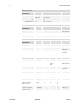
Piranha HS 4x User’s Manual Item (when programmable configuration the options are separated with a | ) Piranha HS 4x Camera Standard Number of Camera Configurations<1,2,3,…> Configuration Definition Cx= HDW, Number of Output Taps, Bit Width, Number of Processing Nodes where Cx is the configuration ID x is <1,2,3…> HDW is Number of Output Taps is <1,2,3…> Bit width is <8, 10,12…> Number Processing Nodes is <1 or 2> VS 4 C1 = Base 4, 8,1 C2 = Base, 4 , 10,
Piranha HS 4x User’s Manual DALSA Corp.
03-32-10040-03 Piranha HS 4x User’s Manual PRELIMINARY DALSA Corp.
Piranha HS 4x User’s Manual 53 Appendix B Command Reference When entering commands, remember that: • A carriage return (CR) ends each command. The linefeed character is ignored. • Values in square brackets are optional. • The camera will answer each command with either a carriage return and line feed followed by "OK >" or "Error x: Error Message >". The ">" is always the last character sent by the camera.
Piranha HS 4x User’s Manual B1 All Available Commands Parameters: t = tap id i = integer value f = real number x1 = pixel start number x2 = pixel end number [ ] = optional parameter 03-32-10040-03 Table 14: All Available Commands Command Syntax Parameters Function Command and Parameter Description calibrate analog gain cag t i Calibrates the analog offset. t = Tap value. 0 for all taps or 1-4 for individual tap selection. i= Line average in a range dependent on the current camera data mode.
Piranha HS 4x User’s Manual DALSA Corp. 55 Command Function Syntax Parameters Command and Parameter Description get camera model get camera parameters get camera serial gcm Returns the camera’s model. gcp Read all of the camera parameters. gcs Read the camera serial number. get camera version get FPN coefficient get line gcv Read the firmware version and FPGA version Read the FPN coefficient.
03-32-10040-03 Piranha HS 4x User’s Manual Command Function Syntax Parameters Command and Parameter Description set analog offset sao t i Sets the analog offset. t = Tap value. 0 for all taps or 1-4 for individual tap selection. i= Controls the digital analog converter (DAC) in a range from 0 to 1023, that sets analog offset. Offset increases with higher values. set binning horizontal sbh i Sets the horizontal binning factor.
Piranha HS 4x User’s Manual DALSA Corp. 57 Command Function Syntax Parameters Command and Parameter Description set lower threshold slt i Sets the lower threshold value that is checked for and reported in the end-of-line statistic. i= Lower threshold value with a range from 0 to 255 DN for 8 bit data modes, and 0 to 1023 DN for 10 bit data modes. set prnu coeff spc i i Set the PRNU coefficient. The first parameter is the pixel number within the range 1 to 2048.
Piranha HS 4x User’s Manual Command Function Syntax Parameters Command and Parameter Description write pixel coeffs wpc Write all current pixel coefficients to EEPROM. write user settings wus Writes all of the user settings to the EEPROM. B2 Error Handling The following tables list the codes for errors, informal messages, and monitoring task messages.
Piranha HS 4x User’s Manual 59 Error Codes Code Description Suggested Cause video level) 22 Analog gain calibration failure Analog gain calibration failure (could not tune the analog gain to obtain targeted video level) 23 CRC check failure while attempting to restore the camera settings Camera setting will initialize to default settings, since restore of USER/FACTORY settings failed (internal micro EE memory failure) 24 Camera settings not saved rus, rfs attempted but settings were not saved
03-32-10040-03 Piranha HS 4x User’s Manual PRELIMINARY DALSA Corp.
Piranha HS 4x User’s Manual 61 Appendix C EMC Declaration of Conformity We, DALSA 605 McMurray Rd.
03-32-10040-03 Piranha HS 4x User’s Manual PRELIMINARY DALSA Corp.
Piranha HS 4x User’s Manual 63 Appendix D Revision History Revision Number Change Description 00 01 Preliminary release Added flat field correction commands: • ROI Region of Interest • CCF Correction Calibrate FPN • CCP Correction Calibrate PRNU • GFC Get FPN Coefficient • SFC Set FPN Coefficient • GPC Get PRNU Coefficient • SPC Set PRNU Coefficient • WPC Write Pixel Coefficients • RPC Reset Pixel Coefficients • DPC Display Pixel Coefficients • LPC Load Pixel Coefficients • EPC Enable Pixel Coefficient
03-32-10040-03 Piranha HS 4x User’s Manual PRELIMINARY DALSA Corp.
Piranha HS 4x User’s Manual 65 Index A D applications, 6 dark calibration, 28 dark patches, 45 data bus, 14 data mode, 20 data rate, 8 debugging, 36, 43 digital data, 14 dimensions, 39 drawing backplate, 12 mechanical, 39 sensor, 7 dynamic range, 8 B back focal distance, 40 baud rate, 19 binning, 23 horizontal, 23 vertical, 24 bit mode, 20 bright lines, 44 C E calibration dark, 28 errors, 30 modes, 36 results, 30 steps, 28 white light, 29 camera control signals, 48 Camera Link, 14 power, 48 referen
Piranha HS 4x User’s Manual analog, 31 digital, 32 subtracting, 31 online help, 18 operating modes, 21 ranges, 8 states, 15 optical interface, 7, 40 output, 14 bit selection, 20 connectors, 12 hot mirror, 40 HR10, 12 I illumination, 40 image sensor, 7 incorrect line rate, 44 input connectors, 12 input voltage, 14 installation, 11 integration stages, 21 interface electrical, 8 mechanical, 8, 39 optical, 7, 40 parameters, 49 P parameters, 18, 51 part numbers, 6 performance specifications, 7–9 pinout,
Piranha HS 4x User’s Manual DALSA Corp.