
User`s manual

Piranha HN RoHS User Manual
03-032-20135-01 Teledyne DALSA
12
Priority
Color of Status LED
Meaning
correction command ccf)
4
Solid Green
Camera is operational and functioning correctly.
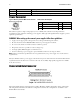
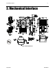
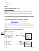
Power Connector
Figure 3: Hirose 6-pin Circular Male—Power Connector Table 3: Hirose Pin Description
The camera requires a single voltage input (+12 to +15VDC). The camera meets all performance
specifications using standard switching power supplies, although well-regulated linear supplies provide
optimum performance.
WARNING: When setting up the camera’s power supplies follow these guidelines:
Apply only the appropriate voltages. Incorrect voltages will damage the camera.
Protect the camera with a fast-blow fuse between power supply and camera.
Do not use the shield on a multi-conductor cable for ground.
Keep leads as short as possible to reduce voltage drop.
Use high-quality linear supplies to minimize noise.
Use an isolated type power supply to prevent LVDS common mode range violation.
Note: Camera performance specifications are not guaranteed if your power supply does not meet these
requirements.
Teledyne DALSA offers a power supply w ith attached 6‘ power cable that meets the Piranha H S camera‘s
requirements, but it should not be considered the only choice. Many high quality supplies are available
from other vendors.
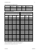
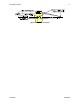
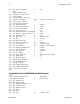
Camera Link Data Connector
Figure 4: Camera Link MDR26 Connector
The Camera Link interface is implemented as a Base, Medium or Full Configuration in the camera. The
following table summarizes the different configurations and lists the configurations available to each
Piranha HS model number.
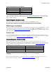
Pin
Description
Pin
Description
1
Min +12 to Max +15VDC
4
GND
2
Min +12 to Max +15VDC
5
GND
3
Min +12 to Max +15VDC
6
GND