TDI Line Scan Camera with Enhanced QE in Near-Infrared Piranha HS NIR Camera User’s Manual HN-80-08k40-xx-R 15 October 2012 03-032-20135-01 www.teledynedalsa.
Piranha HN RoHS User Manual © 2012 Teled yne DALSA. All inform ation provid ed in this manual is believed to be accurate and reliable. No responsibility is assum ed by Teled yne DALSA for its use. Teled yne DALSA reserv es the right to make changes to this inform ation w ithout notice. Reprod uction of this manual in whole or in part, by any m eans, is prohibited w ithout prior perm ission having been obtained fr om Teled yne DALSA. About Teledyne Technologies and Teledyne DALSA, Inc.
Piranha HN RoHS User Manual 3 Contents Contents _____________________________________________________________________________ 3 1. The Piranha HS NIR Camera ______________________________________________________________ 5 Camera Highlights ............................................................................................................................................................. 5 Camera Performance Specifications ............................................................................
Piranha HN RoHS User Manual Setting the Camera Link Mode ....................................................................................................................... 37 Setting the Camera Throughput ..................................................................................................................... 37 Setting the Pixel Readout Direction ................................................................................................................
Piranha HN RoHS User Manual 5 1.
Piranha HN RoHS User Manual Description The Piranha H S N IR cam era fam ily rep resent Teled yne DALSA's latest generation of high sensitivity, TDI based cam eras. The cam era fam ily m axim izes system throu ghp u t. All cam eras are cap able of bid irectionality w ith u p to 256 stages of integration. Applications This cam era is id eal for ap p lications requ iring high sp eed , su p erior im age qu ality, and high resp onsivity in visible and N IR light.
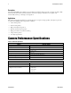
Piranha HN RoHS User Manual 7 Cam era Size Mechanical Interface HN-80-08k40 80 (l) x 150 (h) x 65 (w ) Mass 650 g Connectors 6 pin m ale H irose, pow er Model MDR26 fem ale, d ata Electrical Interface HN-80-08k40 Model + 12 to + 15 ± 5 % Volts DC Input Voltage Pow er Dissipation 18.
Piranha HN RoHS User Manual All values are referenced at 8-bit. 1. Maxim um using highest Cam era Link m od e and m axim um line rate. 2. Measured at the front plate. Image Sensor The cam era u ses Teled yne DALSA‘s new est bid irectional TDI sensors. The cam era can be configu red to read ou t in either Forw ard or Reverse CCD shift d irection. Read ou t d irection is controlled by the softw are com m and scd.
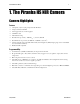
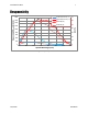
Piranha HN RoHS User Manual 9 1800 HS-8K Responsivity: 1x 1600 HN-8K Responsivity: 1x HN-8K QE (%) 1400 HS-8K QE (%) 1200 70 60 50 1000 40 800 30 600 QE (%) Responsivity DN8bit/(nJ/cm2) Responsivity 20 400 10 200 0 400 500 600 700 800 900 1000 0 1100 Optical Wavelength (nm) Figure 2: Responsivity Teledyne DALSA 03-032-20135-01
Piranha HN RoHS User Manual 2. Quick, Simple Steps to Acquire an Image For u sers w ho are fam iliar w ith Cam era Link cam eras, have a basic u nd erstand ing of their im aging requ irem ents, and w ho are p rim arily interested in evalu ating the cam era, an overview of the step s requ ired to get this cam era op erational and acqu ir ing im ages qu ickly can be fou nd in Ap p end ix B: Qu ick Setu p and Im age Acqu isition .
Piranha HN RoHS User Manual 11 2. Camera Hardware Interface Installation Overview When installing you r cam era, you shou ld take these step s: This installation overview assumes you have not installed any system components yet. 1. Pow er d ow n all equ ip m ent. 2. Follow the m anu factu rer‘s instru ctions to install the fram e grabber (if ap p licable). Be sure to observe all static precautions. Install any necessary im aging softw are. 3. 4.
Piranha HN RoHS User Manual Priority Color of Status LED Meaning correction com m and ccf) 4 Solid Green Cam era is operational and functioning correctly. Power Connector Figure 3: Hirose 6-pin Circular Male—Power Connector Table 3: Hirose Pin Description Pin Description Pin Description 1 Min +12 to Max +15VDC 4 GN D 2 Min +12 to Max +15VDC 5 GN D 3 Min +12 to Max +15VDC 6 GN D The cam era requ ires a single voltage inp u t (+12 to +15VDC).
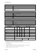
Piranha HN RoHS User Manual 13 Table 4: Camera Link Hardware Configuration Summary Configuration 8 Bit Ports Serializer Bit Supported Width Number of Chips Number of MDR26 Connectors Base A, B, C 28 1 1 Med ium A, B, C, D, E, F 28 2 2 Full A, B, C, D, E, F, G, H 28 3 2 Table 5: Camera Link Connector Pinout Medium and Full Configurations Up to an additional 2 Channel Link Chips Camera Right Angle Channel Cable Connector Frame Link Signal Name Grabber Base Configuration One Channel Link C
Piranha HN RoHS User Manual Table 6: Teledyne DALSA Camera Control Configuration Signal Configuration CC1 CC2 CC3 CC4 EXSYN C Spare Forw ard Spare See Cam era Link Configu ration Tables for the com p lete Teled yne DALSA Cam era Link configu ration tables, and refer to the Teled yne DALSA Web site, Know led ge Center ap p lication notes, for the official Cam era Link d ocu m ents. Input Signals, Camera Link The cam era accep ts control inp u ts throu gh the Cam era Link MDR26F connector.
Piranha HN RoHS User Manual 15 3.
Piranha HN RoHS User Manual Lens Mounts Model Number H N -80 Lens Mount Options M72x0.75 thread . Optical Interface Illumination The am ou nt and w avelengths of light requ ired to cap tu re u sefu l im ages d ep end on the p articu lar ap p lication. Factors inclu d e the natu re, sp eed , and sp ectral cha racteristics of objects being im aged , exp osu re tim es, light sou rce characteristics, environm ental and acqu isition system sp ecifics, and m ore.
Piranha HN RoHS User Manual 17 Figure 6: Primary Points in a Lens System Teledyne DALSA 03-032-20135-01
Piranha HN RoHS User Manual 4. Software Interface: How to Control the Camera All cam era featu res can be controlled throu gh the serial interface. The cam era can also b e u sed w ithou t the serial interface after it has been set u p correctly. Fu nctions available inclu d e: Controlling basic cam era fu nctions su ch as gain and sync signal sou rce. Flat field correction. Mirroring and read ou t control. Generating a test p attern for d ebu gging.
Piranha HN RoHS User Manual 19 y = p ixel row nu m ber Example: To return the current camera settings gcp Camera Help Screen For qu ick help , the cam era can retu rn all available com m and s and p aram eters throu gh the serial interface. There are tw o d ifferent help screens available. One lists all of the available com m and s to configu re cam era op eration.
gsf h ? lpc rc rfs roi rpc rus sab sbh sbv scd sdh sdv sem sfc sg smm sot spc spr ssb ssf ssg ssn stg svm tdi ugr vt vv wfc wpc wus OK> Piranha HN RoHS User Manual get signal frequency m help single command help s load pixel coefficients reset camera restore factory settings region of interest xyxy reset pixel coeffs restore user settings set add background i set binning horizontal m set binning vertical m set ccd direction i set digital horizontal binningm set digital vertical binning m set exposure
Piranha HN RoHS User Manual gla gsf h ? rc rfs rus sab sbh sbv scd sdh sem sg smm sot spr ssb ssf ssg ssn stg svm tdi ugr vt vv wus OK> 21 get line average xx get signal frequency m help single command help s reset camera restore factory settings restore user settings set add background i set binning horizontal m set binning vertical m set ccd direction i set digital horizontal binningm set exposure mode m set gain f set mirroring mode i set output throughput m set prnu range xxi set subtract background
Piranha HN RoHS User Manual ccf cpa 2 (fp n calibration) 16000 (p rnu calibrated to an average p ixel valu e of 4000) Command Categories The follow ing d iagram categorizes and lists all of the cam era‘s com m and s. This chap ter is organized by com m and category.
Piranha HN RoHS User Manual 23 Sensor Output Format Selecting TDI or Area Mode Operation The cam era has the ability to op erate in either TDI or Area Mod e. In Area Mod e, the cam era op erates as an area array cam era u sin g a tw o d im ensional array of p ixels. Area Mod e is u sefu l for aligning the cam era to you r w eb d irection or w hen you need a rectangu lar 2D im age and the lighting su p p orts a fu ll fram e im ager.
Piranha HN RoHS User Manual Setting the Camera’s CCD Shift Direction Purpose: Syntax: Syntax Elem ents: When in TDI Mod e, selects the forw ard or reverse CCD shift d irection or external d irection control. This accom m od ates object d irection change on a w eb and allow s you to m ount the cam era ―upsid e d ow n‖. In Area Mod e, selects the vertical read out d irection. This allow s you to m irror the im age vertically or m oun t the cam era ―upsid e d ow n‖.
Piranha HN RoHS User Manual 25 Increasing Sensitivity with Binning Binning increases the cam era‘s light sensitivity by d ecreasing horizontal and / or vertical resolu tion —the charge collected by ad jacent p ixels is ad d ed together. Binning is also u sefu l for increasing fram e rate (vertical binning) or increasing the p ixel p itch.
03-032-20135-01 Piranha HN RoHS User Manual Teledyne DALSA
Piranha HN RoHS User Manual 27 Figure 10: Relationship between EXSYNC and binning illustrated Setting Horizontal Analog Binning Purpose: Syntax: Syntax Elem ents: N otes: Increases the horizontal pixel pitch and light sensitivity by decreasing horizontal resolution. The am ount of d ata being sent from the cam era is red uced by the horizontal binning factor. Different fram e grabber files are need ed for d ifferent horizontal binning factors. sbh m m H orizontal analog binning value.
Piranha HN RoHS User Manual In this exam p le a region of interest is set to inclu d e p ixels 4 to 9 and horizontal binning is set to 2. Becau se p ixel 3 is now inclu d ed in the sam e d ata grou p as p ixel 4, the region of interest w ill now inclu d e the d ata from p ixel 3. Also, p ixel 10 is inclu d ed in the sam e d ata grou p as p ixel 9, so p ixel 10 is now p art of the region of interest.
Piranha HN RoHS User Manual 29 Setting Vertical Digital Binning Syntax: Syntax: Increases the vertical pixel pitch and light sensitivity by d ecreasing vertical resolution. Vertical binning in TDI Mod e should only be used if your w eb‘s shaft encod er provid es a red uced ratio of pulses to m atch w eb speed . sdv i Syntax Elem ents: i Vertical d igital binning value. Available values are 1 (factory setting, no binning), 2, or 4.
Piranha HN RoHS User Manual Exposure Mode and Line/Frame Rate How to Set Exposure Mode and Line/Frame Rate You have a choice of op erating the cam era in one of tw o exp osu re m od es. Dep end ing on you r m od e of op eration, the cam era‘s line/ fram e rate (synchronization) can be generated internally throu gh the softw are com m and ssf or set externally w ith an EXSYN C signal (CC1). When op erating in TDI Mod e, it is im p ortant that the line rate u sed m atches the w eb sp eed .
Piranha HN RoHS User Manual 31 Exposure Modes in Detail Mode 3: External Trigger, Maximum Exposure Time Figure 12: Mode 3 Timing Mode 7: Internal Frame Rate, Maximum Exposure Time In this m od e, the fram e rate is set internally u sing the ssf com m and w ith a m axim u m exp osu re tim e. Note: In TDI m od e the fram e p eriod equ als the line p eriod .
Piranha HN RoHS User Manual Setting Frame Rate Purpose: Syntax: Syntax Elem ents: Sets the cam era‘s fram e rate in H z. Cam era m ust be operating in exposure m od e 7. ssf i i Set the fram e rate to a value from : TDI : 1-34246 Area : 1-130 N otes: Value round ed up/ d ow n as required . The m axim um line/ fram e rate is affected by horizontal and vertical binning factors, throughput setting, Cam era Link m od e, and num ber of CCD integration stages.
Piranha HN RoHS User Manual 33 Maximum Line Rate Calculations The m axim u m line rate in the cam era is lim ited by either the Cam era Link row tim e or the sensor row line tim e. The follow ing calcu lations are u sed to d eterm ine the m axim u m line rate.
Piranha HN RoHS User Manual Camera Output Format How to Configure Camera Output The cam eras offer great flexibility w hen configu ring you r cam era ou tp u t. Using the clm com m and , you d eterm ine the cam era‘s Cam era Link configu ration, nu m ber of ou tp u t tap s, and bit d ep th. Using the sot com m and , you d eterm ine the cam era‘s ou tp u t rate. These tw o com m and s w ork together to d eterm ine you r final cam era ou tp u t configu ration.
Piranha HN RoHS User Manual 35 Table 8: HN-80-08k40 Configurations Camera Link Mode Configuration (Controlled command) Command Camera Link Camera Link Configuration Taps clm 2 Base 2 Cam era Link tap s w here: 1 = Od d Pixels 2 = Even Pixels by clm Bit Depth 8 Readout Direction (Controlled by smm command) Pixel Rate Configuration (Controlled by sot command) smm 0 = CL tap 1(1, 3 to sot 80 = 40 MH z 8191) strobe CL tap 2(2, 4 to 8192) sot 160 = 80 MH z strobe smm 1 = CL tap 1(8192, 8190 to 2) C
Piranha HN RoHS User Manual Camera Link Mode Configuration (Controlled by clm command) Command Camera Link Camera Link Bit Configuration Taps Depth Readout Direction (Controlled by smm command) Pixel Rate Configuration (Controlled by sot command) CL tap 4(8189, 8185 to 1) clm 21 Fu ll 8 Cam era Link tap s w here: 8 smm 0 = CL tap 1(1, 9 to sot 320 = 40 MH z 8185) strobe (m ax line rate 18814H z) CL tap 2(2, 10 to th 1 = Every 4 Od d Pixel th 2 = Every 4 Even Pixel th 3 = Every 4 Od d Pixel
Piranha HN RoHS User Manual 37 Setting the Camera Link Mode Purpose: Syntax: Syntax Elem ents: N otes: Related Com m and s Exam ple: Sets the cam era‘s Cam era Link con figuration, num ber of Cam era Link taps and d ata bit d epth. Refer to the tables on the previous pages to d eterm ine w hich configurations are valid for your cam era m od el and how this com m and relates to other cam era configuration com m and s.
Piranha HN RoHS User Manual Setting the Pixel Readout Direction Purpose: Syntax: Syntax Elem ents: N otes: Sets the tap read out from left to right or from right to left. This com m and is useful if the cam era m ust be m ounted upsid e d ow n. smm i i Read out d irection. Allow able values are: 0 = All pixels are read out from left to right. 1 = All pixels are read out from right to left. To obtain the current read out d irection, use the com m and gcp or get smm.
Piranha HN RoHS User Manual 39 Setting a Region of Interest Purpose: Syntax: Syntax Elem ents: Sets the pixel range used to collect the end -of-line statistics and sets the region of pixels used in the ccg, cpa, gl, gla, and ccf com m and s. In m ost applications, the field of view exceed s the required object size and these extraneous areas should be ignored . It is recom m end ed that you set the region of interest a few pixels insid e the actu al useable im age.
Piranha HN RoHS User Manual Figure 18: Signal Processing Chain Digital Processing 1. Fixed p attern noise (FPN ) calibration (calcu lated u sing the ccf com m and ) is u sed to su btract aw ay ind ivid u al p ixel d ark cu rrent and d ark offset . 2. Digital gain has 3 m ethod s for ad ju sting the cam era d igital gain. The ccg com m and ad ju sts the d igital gain for a gain target. The sg com m and allow s the u ser to ad ju st the gain in d B.
Piranha HN RoHS User Manual 41 Setting the Camera Gain Calibrating Camera Gain Purpose: Syntax: Syntax Elem ents: Instead of m anually setting the d igital gain to a specific value, the cam era can d eterm ine appropriate gain values. This com m and calculates and sets the d igital gain. ccg i i Calculation target value in a range from 4096 to 16064 DN (14 bit LSB). N otes: Exam ple: The algorithm calculates the gain of the 8 h tap to set the tap m ean to the user target.
Piranha HN RoHS User Manual Calibrating the Camera to Remove Non-Uniformity (Flat Field Correction) Flat Field Correction Overview This cam era has the ability to calcu late correction coefficients in ord er to rem ove non -u niform ity in the im age w hen op erating in TDI Mod e. This vid eo correction op erates on a p ixel-by-p ixel basis and im p lem ents a tw o p oint correction for each p ixel.
Piranha HN RoHS User Manual 43 4. The brightest p ixel shou ld be slightly below the target ou tp u t. 5. When 6.25% of p ixels from a single row w ithin the region of interest are clip p ed , flat field correction resu lts m ay be inaccu rate. 6. Correction resu lts are valid only for the cu rrent sta ge selection. If you change the nu m ber of stages, it is recom m end ed that you recalcu late you r coefficients. 7. Correction resu lts are valid only for the cu rrent gain and offset valu es.
Piranha HN RoHS User Manual How to Perform Flat Field Correction 1 Setup the camera operating environm ent (ie. Line rate, CCD Shift Direction, exposure, offset, gain, etc) Digital Offset and gain. Background subtract values should be set to zero. (ssb 0, sab 0, ssg 0) Select the User Set (ssn 1, 2, 3 or 4) N OTE: Item s highlighted in GREY are not necessary to perform , unless you require doing so. 2 Steps 1, 4 and 5 are usually only needed to be performed.
Piranha HN RoHS User Manual 45 Performing FPN Correction Syntax: Syntax: N otes: Related Com m and s: Exam ple: Perform s FPN correction and elim inates FPN noise by subtracting aw ay ind ivid ual pixel d ark current. For a com plete d escription on how to use this com m and , see the Flat Field Correction Overview . ccf Before perform ing this com m and , stop all light from entering the cam era. (Tip: cover lens w ith a lens cap.) Perform FPN correction before PRN U correction.
Piranha HN RoHS User Manual 4 = Sam e calculation above, only in ROI. The calculation is perform ed for all sensor pixels but w arnings are only applied to pixels in the region of interest. This algorithm is useful for achieving uniform output across m ultiple cam eras. It is im portant that the target value (set w ith the next param eter) is set to be at least equal to the highest pixel across all cam eras so that all pixels can reach the highest pixel value d uring calibration.
Piranha HN RoHS User Manual Related Com m and s Exam ple 47 ssg ssb 500 Setting Digital Gain Purpose: Im proves signal output sw ing after a background subtract. When subtracting a d igital value from the d igital vid eo signal, using the ssb com m and , the output can no longer reach its m axim um . Use the this com m and to correct for this w here: ssg value = Syntax: Syntax Elem ents: max output value max output value - ssb value ssg i i Gain setting. The gain ranges are 0 to 61438.
Piranha HN RoHS User Manual Saving and Restoring Settings Saving and Restoring Factory and User Settings Figure 19: Saving and Restoring Overview Factory Settings You can restore the original factory settings, inclu d ing the factory calibrated p ixel coefficient set, at any tim e u sing the com m and rfs. User Settings There are tw o m ain sets of u ser settings: Area Mod e u ser settings and TDI Mod e u ser settings.
Piranha HN RoHS User Manual 49 START User issues wus command Camera is operating in Area Mode Area Mode User Settings Camera is operating in TDI Mode TDI Mode User Settings All settings saved for Area Mode only All settings, except pixel coefficients, saved for TDI Mode only. Figure 20: How User Settings are Stored in the HN-xx Cameras after issuing the wus Command You can save or restore you r u ser settings to non -volatile m em ory u sing the follow ing com m and s.
Piranha HN RoHS User Manual Restores the Factory User Settings Purpose: Syntax: N otes: Exam ple: See also: Restores the factory user settings for the current d irection to the current set num ber. rfs Available in TDI or area m od e for sets 1 to 4. rfs wus, rus Selecting the Set Number Purpose: Syntax: Syntax Elem ents: When saving and load ing cam era settings, you have a choice of saving up to four d ifferent sets and load ing from five d ifferent sets (four user and one factory).
Piranha HN RoHS User Manual 51 Saving and Restoring PRNU and FPN Coefficients Pixel coefficient sets are saved sep arately for Forw ard and Reverse d irection, d ep end ing on w hich d irection the cam era is op erating in w hen the wpc or wfc com m and is issu ed . It is im p ortant that you save p ixel coefficients before sw itching CCD shift d irect ion or cu rrent coefficient valu es w ill be lost. START Note: Available in TDI Mode only. User issues wpc or wfc command.
Piranha HN RoHS User Manual Rebooting the Camera The com m and rc reboots the cam era. The cam era starts u p w ith the last saved settings and the bau d rate u sed before reboot. Previou sly saved p ixel coefficients are also restored . Diagnostics Generating a Test Pattern Purpose: Syntax: Syntax Elem ents: N otes: Exam ple: Generate a test pattern to aid in system d ebugging. The test patterns are useful for verifying proper tim ing and connections betw een the cam era and the fram e grabber.
Piranha HN RoHS User Manual 53 Returning a Single Line of Video Purpose: Syntax: Syntax Elem ents: Returns a com plete line of video (w ith out pixel coefficients or test pattern) d isplaying one pixel value after another. It also d isplays the m inim um , m axim um , and m ean value of the line sam pled w ithin the region of interest (the region of interest com m and is explained in Setting a Region of Interest).
N otes: Related Com m and s: Exam ple: Piranha HN RoHS User Manual x1 If x2 Analog gain, analog offset, d igital offset, background subtract, and d igital system gain are applied to the d ata. FPN and PRN U coefficients are not includ ed in the d ata. Values returned are in 12 bit DN . Available in TDI Mod e only. then x2 is forced to be x1. css, roi gla 10 20 Temperature Measurement The tem p eratu re of the cam era can be d eterm ined by u sing the vt com m and .
Piranha HN RoHS User Manual 55 GCP Screen Cam era Mod el N o.: Sensor Serial N o.: Description H N -xx-xxxxx-xx-R Cam era m od el nu m ber. xxxxxxxxx Sensor serial nu m ber. Firm w are Design Rev.: xx-xx-xxxxx-xx Firm w are d esign revision nu m ber. CCI Version: xx-xxx-xxxxx-xx Cam era control inform ation. FPGA Version: xx-xx-xxxx-xx DSP d esign revision nu m ber. SSN 0 Set N u m ber Vid eo Mod e: vid eo Cu rrent vid eo m od e valu e set w ith the svm com m and .
Piranha HN RoHS User Manual GCP Screen Backgrou nd Ad d ition: 0 Description Backgrou nd ad d ition settings set w ith the sab com m and . Backgrou nd Su btract: Backgrou nd su btract settings set w ith the ssb com m and . 0 Returning Camera Settings with Get Commands You can also retu rn ind ivid u al cam era settings by inserting a ― get” in front of the com m and that you w ant to qu ery.
Piranha HN RoHS User Manual 57 Appendix A: Error Handling and Command List Error Handling The follow ing table lists w arning and error m essages and p rovid es a d escrip tion and p ossible cau se. Warning m essages are retu rned w hen the cam era ca nnot m eet the fu ll valu e of the requ est; error m essages are retu rned w hen the cam era is u nable to com p lete the requ est.
Piranha HN RoHS User Manual Error Messages Error 05: Com m and unavailable in this m od e> E.g. SSF w hen in SEM 3 Error 06: Tim eout> Com m and not com pleted in tim e. E.g. CCF in SEM 3 w hen no external EXSYN C is present. Error 07: Cam era settings not saved > Ind icates that user settings have been corrupted by turning off the pow er w hile executing the WUS com m and . Must build up new settings from factory and re-save w ith WUS.
Piranha HN RoHS User Manual Mnemonic calculate PRN U algorithm 59 Syntax Parameters Description cpa m i Perform s PRN U calibration accord ing to the selected algorithm . The first param eter is the algorithm w here m is: 2 = Calculates the PRN U coefficients using the entered target value as show n below : The calculation is perform ed for all sensor pixels but w arnings are only applied to pixels in the region of interest.
Piranha HN RoHS User Manual Mnemonic Syntax restore factory settings rfs region of interest roi reset pixel coeffs rpc restore user settings rus Parameters Description Restore the cam era‘s factory settings. FPN and PRN U coefficients reset to 0. x1 y1 x2 y2 Sets the pixel range affected by the ccg, gl, gla, ccf, cpa and ccp com m and s. The param eters are the pixel start and end values (x1 and x2) and the colum n start and end values (y1 and y2) in a range from 1 to 8192.
Piranha HN RoHS User Manual Mnemonic 61 Syntax Parameters Description set sync frequency ssf f Set the fram e rate to a value from : TDI: 1-34246 Area: 1-130 Value round ed up/ d ow n as required . set system gain ssg i Set the d igital gain. i = System gain in a range from 0 to 61438. The digital vid eo values are m ultiplied by this num ber. set set num ber ssn i Sets the ―set‖ num ber from w here these values are load ed and saved . i = set num ber in a range from 0 to 4.
Piranha HN RoHS User Manual Appendix B: Quick Setup and Image Acquisition If you are fam iliar w ith the op eration of Cam era Link cam eras and have an u nd erstand ing of im aging fu nd am entals, the follow ing step s w ill show you how to qu ickly set u p this cam era and begin acqu iring im ages. 1. On Power Up The cam era has been calibrated and configu red at the factory to be read y for you r evalu ation w hen first p ow ered u p .
Piranha HN RoHS User Manual 63 The ap p roxim ate location of the sensor p osition is at the first groove in the sid e of the case, back from the front face as show n in the m echanical illu stration . 4. Camera Timing & Control It is easiest and qu ickest to evalu ate the cam era u sing the internal tim ing setu p s for line rate and exp osu re tim e. Since w e recom m end starting w ith Cam era Link m ed iu m m od e, set a su itable line rate less than 20 KH z, u sing the ‗ssf‘ com m and .
Piranha HN RoHS User Manual PRNU Correction The PRN U correction is m ore involved since the key requ irem ent is that the cam era be exp osed to a u niform illu m ination w ith no p attern in the im age. The light level shou ld be at the sam e level over the w hole w id th of the sensor. Then the cp a com m and is issu ed . As w ell, the highest p ixel valu e m u st not exceed the target valu e. (The cp a com m and generates 2 ou tp u ts.
Piranha HN RoHS User Manual 65 7. Restoring Factory Calibration: lpc Comand The calibration coefficients can be saved in the cam era in 5 d ifferent ―sets‖, nu m bered from zero to fou r. The factory calibrations are saved in set zero and you cannot overw rite the ―zero‖ settings. To op erate in ―set zero‖ you u se the ―set set nu m ber‖ or ssn com m and by typ ing ssn 0. N ext, to restore the factory coefficients, you need the ―load p ixel coefficients‖ or lp c com m and .
Piranha HN RoHS User Manual Appendix C: EMC Declaration of Conformity We, Teled yne DALSA 605 McMu rray Rd .
Piranha HN RoHS User Manual 67 Appendix D: CCD Handling Instructions Electrostatic Discharge and the CCD Sensor Cam eras contain charge-cou p led d evice (CCD) im age sensors, w hich are m etal oxid e sem icond u ctor (MOS) d evices and are su scep tible to d am age from electrostatic d ischarge (ESD).
Piranha HN RoHS User Manual Cleaning the Sensor Window 1. Use com p ressed air to blow off loose p articles. This step alone is u su ally su fficient to clean the sensor w ind ow . 2. If fu rther cleaning is requ ired , u se a lens w ip er m oistened w ith alcohol or a cetone. 3. We recom m end u sing lint-free ESD-safe cloth w ip ers that d o not contain p articles that can scratch the w ind ow .
Piranha HN RoHS User Manual 69 Revision History Revision Number Change Description Date 00 01 Revised Prelim inary Version for Consignm ent Cam eras -Table 1: Upd ated perform ance specifications (w ere TBD) -Inserted Section 2: Quick, Simple Steps to Acquire an Im age -Inserted Append ix B: Quick Setup and Im age Acquisition -Append ix C: Date of issue upd ated (w as TBD) August 18, 2012 October 15, 2012 Teledyne DALSA 03-032-20135-01
Piranha HN RoHS User Manual Index overview , 30 EXSYN C, 14 w ith Binning, 25 A ap p lications, 6 F B fiber-op tic light sou rces, 16 filters, 16 flat field correction, 44 FVAL, 14 binning, 25 horizontal, 27, 28 vertical, 28, 29 C calibrating the cam era, 42 calibration overview , 42 step s, 42 cam era m essages, 57 ou tp u t configu ration, 34 cam era control signals, 14 Cam era Link configu rations, 13 connector, 12 m od e, 37 ou tp u ts, 14 cam era settings retrieving, 54 saving, 48 clocking s
Piranha HN RoHS User Manual 71 m od es, 30 op tical interface, 16 cleaning, 67 serial interface, 18 d efau lts, 18 settings factory, 21 STROBE, 14 P p ow er gu id elines, 12 su p p ly, 12 R T tap read ou t d irection, 38 TDI Mod e, 23 tem p eratu re m easu rem ent, 54 test p atterns, 52 tim ing m od e 3, 31 m od e 7, 31 read ou t configu ring, 34 d irection, 38 rebooting, 52 resolu tion, 6 resp onsivity, 7 Revision H istory, 69 roi, 39 V S SEE, 7 sensitivity level, 23 sensor, 8 Teledyne DALSA vid