
User`s manual

Piranha HN RoHS User Manual
Teledyne DALSA 03-032-20135-00
13
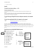
Table 4: Camera Link Hardware Configuration Summary for Piranha HN-xx Models
Configuration 8 Bit Ports
Supported
Serializer Bit
Width
Number of
Chips
Number of MDR26
Connectors
Base A, B, C 28 1 1
Medium A, B, C, D, E, F 28 2 2
Full A, B, C, D, E, F, G, H 28 3 2
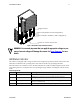
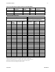
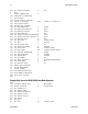
Table 5: Camera Link Connector Pinout
Medium and Full Configurations Base Configuration
Up to an additional 2 Channel Link Chips One Channel Link Chip + Camera
Control + Serial Communication
Camera
Connector
Right Angle
Frame
Grabber
Channel
Link Signal
Cable
Name
Camera
Connector
Right Angle
Frame
Grabber
Channel
Link Signal
1 1 inner shield Inner Shield 1 1 inner shield
14
14
inner shield
Inner Shield
14
14
inner shield
2
25
Y0-
PAIR1-
2
25
X0-
15
12
Y0+
PAIR1+
15
12
X0+
3
24
Y1-
PAIR2-
3
24
X1-
16 11 Y1+ PAIR2+ 16 11 X1+
4 23 Y2- PAIR3- 4 23 X2-
17 10 Y2+ PAIR3+ 17 10 X2+
5 22 Yclk- PAIR4- 5 22 Xclk-
18 9 Yclk+ PAIR4+ 18 9 Xclk+
6 21 Y3- PAIR5- 6 21 X3-
19 8 Y3+ PAIR5+ 19 8 X3+
7 20 100 ohm PAIR6+ 7 20 SerTC+
20 7 terminated PAIR6- 20 7 SerTC-
8 19 Z0- PAIR7- 8 19 SerTFG-
21 6 Z0+ PAIR7+ 21 6 SerTFG+
9 18 Z1- PAIR8- 9 18 CC1-
22
5
Z1+
PAIR8+
22
5
CC1+
10
17
Z2-
PAIR9+
10
17
CC2+
23
4
Z2+
PAIR9-
23
4
CC2-
11 16 Zclk- PAIR10- 11 16 CC3-
24 3 Zclk+ PAIR10+ 24 3 CC3+
12 15 Z3- PAIR11+ 12 15 CC4+
25 2 Z3+ PAIR11- 25 2 CC4-
13 13 inner shield Inner Shield 13 13 inner shield
26 26 inner shield Inner Shield 26 26 inner shield
Notes:
*Exterior Overshield is connected to the shells of the connectors on both ends.
**3M part 14X26-SZLB-XXX-0LC is a complete cable assembly, including connectors.
Unused pairs should be terminated in 100 ohms at both ends of the cable.
Inner shield is connected to signal ground inside camera