High Sensitivity Line Scan CCD Camera with Enhanced QE in Near-Infrared Piranha HN Camera User’s Manual HN-80-08k40-xx-R 18-August-2012 03-032-20135-00 www.teledynedalsa.
Piranha HN RoHS User Manual 2 © 2012 Teledyne DALSA. All information provided in this manual is believed to be accurate and reliable. No responsibility is assumed by Teledyne DALSA for its use. Teledyne DALSA reserves the right to make changes to this information without notice. Reproduction of this manual in whole or in part, by any means, is prohibited without prior permission having been obtained from Teledyne DALSA. About Teledyne Technologies and Teledyne DALSA, Inc.
Piranha HN RoHS User Manual 3 Contents 1. The Piranha HN Camera _________________________________________________________________ 5 Camera Highlights .............................................................................................................................................................5 Camera Performance Specifications ..................................................................................................................................6 Image Sensor ......................
Piranha HN RoHS User Manual Setting the Pixel Readout Direction................................................................................................................36 Setting a Region of Interest ............................................................................................................................37 Digital Signal Processing Chain ......................................................................................................................
Piranha HN RoHS User Manual 5 1.
Piranha HN RoHS User Manual 6 Description The Piranha HN camera family represent Teledyne DALSA's latest generation of high sensitivity, TDI based cameras. The Piranha HN family maximizes system throughput. All cameras are capable of bidirectionality with up to 256 stages of integration. Applications The Piranha HN family is ideal for applications requiring high speed, superior image quality, and high responsivity in visible and NIR light.
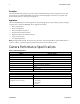
Piranha HN RoHS User Manual 7 Camera Size Mechanical Interface HN-80-08k40 80 (l) x 150 (h) x 65 (w) Mass < 800 g Connectors 6 pin male Hirose, power Model MDR26 female, data Electrical Interface HN-80-08k40 Model Input Voltage Power Dissipation2 + 12 to + 15 ± 5 % Volts DC 18.
Piranha HN RoHS User Manual 8 • All Typ specifications are measured at 25 °C. • All values are referenced at 12-bit. 1. Maximum using highest Camera Link mode and maximum line rate. 2. Measured at the front plate. Image Sensor The camera uses Teledyne DALSA’s newest bidirectional TDI sensors. The camera can be configured to read out in either Forward or Reverse CCD shift direction. Readout direction is controlled by the software command scd.
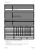
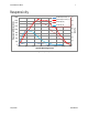
Piranha HN RoHS User Manual 9 1800 HS-8K Responsivity: 1x 1600 HN-8K Responsivity: 1x HN-8K QE (%) 1400 HS-8K QE (%) 1200 70 60 50 1000 40 800 30 600 QE (%) Responsivity DN/(nJ/cm2) Responsivity 20 400 10 200 0 400 500 600 700 800 900 1000 0 1100 Optical Wavelength (nm) Figure 2: Responsivity Teledyne DALSA 03-032-20135-00
Piranha HN RoHS User Manual 10 2. Camera Hardware Interface Installation Overview When installing your camera, you should take these steps: This installation overview assumes you have not installed any system components yet. 1. Power down all equipment. 2. Follow the manufacturer’s instructions to install the frame grabber (if applicable). Be sure to observe all static precautions. 3. Install any necessary imaging software. 4. Before connecting power to the camera, test all power supplies.
Piranha HN RoHS User Manual 11 Diagnostic LED Camera Link (Medium or Full Configuration) Camera Link (Base, Medium or Full Configuration) +12VDC to +15VDC and Ground Figure 3: Piranha HN-xx Input and Output Connectors ! WARNING: It is extremely important that you apply the appropriate voltages to your camera. Incorrect voltages will damage the camera. See Power Connector for more details.
Piranha HN RoHS User Manual 12 Power Connector Figure 4: Hirose 6-pin Circular Male—Power Connector Table 3: Hirose Pin Description Pin Description Pin Description 1 Min +12 to Max +15VDC 4 GND 2 Min +12 to Max +15VDC 5 GND 3 Min +12 to Max +15VDC 6 GND The camera requires a single voltage input (+12 to +15VDC). The camera meets all performance specifications using standard switching power supplies, although well-regulated linear supplies provide optimum performance.
Piranha HN RoHS User Manual 13 Table 4: Camera Link Hardware Configuration Summary for Piranha HN-xx Models Configuration 8 Bit Ports Serializer Bit Number of Supported Width Chips Number of MDR26 Connectors Base A, B, C 28 1 1 Medium A, B, C, D, E, F 28 2 2 Full A, B, C, D, E, F, G, H 28 3 2 Table 5: Camera Link Connector Pinout Medium and Full Configurations Up to an additional 2 Channel Link Chips Camera Right Angle Channel Cable Connector Frame Link Signal Name Grabber Base Configura
Piranha HN RoHS User Manual 14 Table 6: Teledyne DALSA Camera Control Configuration Signal Configuration CC1 EXSYNC CC2 Spare CC3 Forward CC4 Spare See Camera Link Configuration Tables for the complete Teledyne DALSA Camera Link configuration tables, and refer to the Teledyne DALSA Web site, Knowledge Center application notes, for the official Camera Link documents. Input Signals, Camera Link The camera accepts control inputs through the Camera Link MDR26F connector.
Piranha HN RoHS User Manual 15 3.
Piranha HN RoHS User Manual 16 Lens Mounts Model Number HN-80 Lens Mount Options M72x0.75 thread. Optical Interface Illumination The amount and wavelengths of light required to capture useful images depend on the particular application. Factors include the nature, speed, and spectral characteristics of objects being imaged, exposure times, light source characteristics, environmental and acquisition system specifics, and more. It is often more important to consider exposure than illumination.
Piranha HN RoHS User Manual 17 Figure 7: Primary Points in a Lens System Teledyne DALSA 03-032-20135-00
Piranha HN RoHS User Manual 18 4. Software Interface: How to Control the Camera All Piranha HN-xx camera features can be controlled through the serial interface. The camera can also be used without the serial interface after it has been set up correctly. Functions available include: • Controlling basic camera functions such as gain and sync signal source. • Flat field correction. • Mirroring and readout control. • Generating a test pattern for debugging.
Piranha HN RoHS User Manual • 19 y = pixel row number Example: To return the current camera settings gcp Camera Help Screen For quick help, the camera can return all available commands and parameters through the serial interface. There are two different help screens available. One lists all of the available commands to configure camera operation. The other help screen lists all of the commands available for retrieving camera parameters (these are called “get” commands).
Piranha HN RoHS User Manual 20 gsf h ? lpc rc rfs roi rpc rus sab sbh sbv scd sdh sdv sem sfc sg smm sot spc spr ssb ssf ssg ssn stg svm tdi ugr vt vv wfc wpc wus OK> get signal frequency m help single command help s load pixel coefficients reset camera restore factory settings region of interest xyxy reset pixel coeffs restore user settings set add background i set binning horizontal m set binning vertical m set ccd direction i set digital horizontal binningm set digital vertical binning m set exposure
Piranha HN RoHS User Manual gla gsf h ? rc rfs rus sab sbh sbv scd sdh sem sg smm sot spr ssb ssf ssg ssn stg svm tdi ugr vt vv wus OK> 21 get line average xx get signal frequency m help single command help s reset camera restore factory settings restore user settings set add background i set binning horizontal m set binning vertical m set ccd direction i set digital horizontal binningm set exposure mode m set gain f set mirroring mode i set output throughput m set prnu range xxi set subtract background
Piranha HN RoHS User Manual 22 (fpn calibration) ccf cpa 2 16000 (prnu calibrated to an average pixel value of 4000) Command Categories The following diagram categorizes and lists all of the camera’s commands. This chapter is organized by command category.
Piranha HN RoHS User Manual 23 Sensor Output Format Selecting TDI or Area Mode Operation The Piranha HN-xx camera has the ability to operate in either TDI or Area Mode. In Area Mode, the camera operates as an area array camera using a two dimensional array of pixels. Area Mode is useful for aligning the camera to your web direction or when you need a rectangular 2D image and the lighting supports a full frame imager.
Piranha HN RoHS User Manual 24 Setting the Camera’s CCD Shift Direction Purpose: Syntax: Syntax Elements: When in TDI Mode, selects the forward or reverse CCD shift direction or external direction control. This accommodates object direction change on a web and allows you to mount the camera “upside down”. In Area Mode, selects the vertical readout direction. This allows you to mirror the image vertically or mount the camera “upside down”. scd i i • Notes: • Readout direction.
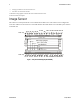
Piranha HN RoHS User Manual 25 Increasing Sensitivity with Binning Binning increases the camera’s light sensitivity by decreasing horizontal and/or vertical resolution—the charge collected by adjacent pixels is added together. Binning is also useful for increasing frame rate (vertical binning) or increasing the pixel pitch. For example, if you set your vertical binning to 2 and your horizontal binning to 2, your pixel size increases from 7µm x 7µm (no binning) to 14 µm x 14 µm (2 x 2 binning).
Piranha HN RoHS User Manual 26 Syntax: Syntax Elements: binning factor. Different frame grabber files are needed for different horizontal binning factors. sbh m m • Notes: Horizontal analog binning value. Available values are 1 (factory setting, no binning) 2, or 4. If you are using horizontal binning, the min, max, and mean statistics generated by the gl or gla command are for every second pixel (or valid data) only (e.g., if sbh 2, every second pixel).
Piranha HN RoHS User Manual Example: 27 • Changing binning values does not automatically alter gain, external frame rate generation, or other functions of the camera. • Pixel numbering remains unchanged for the roi, gl, gla, gfc , sfc , gpc, and spc commands. Refer to Figure 19 for an explanation of pixel numbering and pixel start and stop values when using a region of interest. • Command sbh set to default (1).
Piranha HN RoHS User Manual 28 Exposure Mode and Line/Frame Rate How to Set Exposure Mode and Line/Frame Rate You have a choice of operating the camera in one of two exposure modes. Depending on your mode of operation, the camera’s line/frame rate (synchronization) can be generated internally through the software command ssf or set externally with an EXSYNC signal (CC1). When operating in TDI Mode, it is important that the line rate used matches the web speed.
Piranha HN RoHS User Manual 29 Exposure Modes in Detail Mode 3: External Trigger, Maximum Exposure Time Figure 12: Mode 3 Timing Mode 7: Internal Frame Rate, Maximum Exposure Time In this mode, the frame rate is set internally using the ssf command with a maximum exposure time. Note: In TDI mode the frame period equals the line period.
Piranha HN RoHS User Manual 30 Setting Frame Rate Purpose: Syntax: Syntax Elements: Sets the camera’s frame rate in Hz. Camera must be operating in exposure mode 7. ssf i i Set the frame rate to a value from: TDI : 1-34246 Area : 1-130 Notes: Related Commands: Example: 03-032-20135-00 Value rounded up/down as required. The maximum line/frame rate is affected by horizontal and vertical binning factors, throughput setting, Camera Link mode, and number of CCD integration stages.
Piranha HN RoHS User Manual 31 Maximum Line Rate Calculations The maximum line rate in the camera is limited by either the Camera Link row time or the sensor row line time. The following calculations are used to determine the maximum line rate. Variables for calculations: • User.SOT = 80 | 160 | 320 | 640 • User.CLM = 2(3) | 15(16) | 21 • User.SBH = 1 | 2 | 4 • User.SDH = 1 | 2 | 4 • User.SBV = 1 | 2 | 4 • User.SDV = 1 | 2 | 4 • User.TDI = 0 | 1 • User.
Piranha HN RoHS User Manual 32 Camera Output Format How to Configure Camera Output The Piranha HN cameras offer great flexibility when configuring your camera output. Using the clm command, you determine the camera’s Camera Link configuration, number of output taps, and bit depth. Using the sot command, you determine the camera’s output rate. These two commands work together to determine your final camera output configuration.
Piranha HN RoHS User Manual 33 Table 8: HN-80-08k40 Configurations Camera Link Mode Configuration (Controlled command) Command Camera Link Camera Link Configuration Taps clm 2 Base 2 Camera Link taps where: 1 = Odd Pixels 2 = Even Pixels by clm Bit Depth 8 Readout Direction (Controlled by smm command) Pixel Rate Configuration (Controlled by sot command) smm 0 = CL tap 1(1, 3 to sot 80 = 40 MHz 8191) 8192) smm 1 = CL tap 1(8192, 8190 to 2) to 1) clm 3 Base 2 Camera Link taps where: 1 = Odd Pixels
Piranha HN RoHS User Manual 34 Camera Link Mode Configuration (Controlled by clm command) Command Camera Link Camera Link Bit Configuration Taps Depth Readout Direction (Controlled by smm command) to 2) to 1) clm 21 Full 8 Camera Link taps where: 1 = Every 4th Odd Pixel 2 = Every 4th Even Pixel 3 = Every 4th Odd Pixel 4 = Every 4th Even Pixel 1 = Every 4th Odd Pixel 2 = Every 4th Even Pixel 3 = Every 4th Odd Pixel 4 = Every 4th Even Pixel 8 CL tap 3(8190, 8186 CL tap 4(8189, 8185 smm 0 = CL tap 1(1
Piranha HN RoHS User Manual 35 Setting the Camera Link Mode Purpose: Syntax: Syntax Elements: Notes: Related Commands Example: Sets the camera’s Camera Link configuration, number of Camera Link taps and data bit depth. Refer to the tables on the previous pages to determine which configurations are valid for your camera model and how this command relates to other camera configuration commands.
Piranha HN RoHS User Manual 36 Setting the Pixel Readout Direction Purpose: Syntax: Syntax Elements: Notes: Sets the tap readout from left to right or from right to left. This command is useful if the camera must be mounted upside down. smm i i • Readout direction. Allowable values are: 0 = All pixels are read out from left to right. 1 = All pixels are read out from right to left. To obtain the current readout direction, use the command gcp or get smm.
Piranha HN RoHS User Manual 37 Setting a Region of Interest Purpose: Syntax: Syntax Elements: Sets the pixel range used to collect the end-of-line statistics and sets the region of pixels used in the ccg, cpa, gl, gla, and ccf commands. In most applications, the field of view exceeds the required object size and these extraneous areas should be ignored. It is recommended that you set the region of interest a few pixels inside the actual useable image. roi x1 y1 x2 y2 x1 Column start number.
Piranha HN RoHS User Manual 38 Figure 18: Signal Processing Chain Digital Processing 1. Fixed pattern noise (FPN) calibration (calculated using the ccf command) is used to subtract away individual pixel dark current and dark offset. 2. Digital gain has 3 methods for adjusting the camera digital gain. The ccg command adjusts the digital gain for a gain target. The sg command allows the user to adjust the gain in dB. The sg command does not have a target component in the command algorithm.
Piranha HN RoHS User Manual 39 Setting the Camera Gain Calibrating Camera Gain Purpose: Syntax: Syntax Elements: Instead of manually setting the digital gain to a specific value, the camera can determine appropriate gain values. This command calculates and sets the digital gain. ccg i i Calculation target value in a range from 4096 to 16064 DN (14 bit LSB). Notes: Example: • The algorithm calculates the gain of the 8h tap to set the tap mean to the user target.
Piranha HN RoHS User Manual 40 Calibrating the Camera to Remove Non-Uniformity (Flat Field Correction) Flat Field Correction Overview This camera has the ability to calculate correction coefficients in order to remove non-uniformity in the image when operating in TDI Mode. This video correction operates on a pixel-by-pixel basis and implements a two point correction for each pixel.
Piranha HN RoHS User Manual 41 3. The camera is capable of operating under a range of 8 to 1, but will clip values larger than this ratio. 4. The brightest pixel should be slightly below the target output. 5. When 6.25% of pixels from a single row within the region of interest are clipped, flat field correction results may be inaccurate. 6. Correction results are valid only for the current stage selection. If you change the number of stages, it is recommended that you recalculate your coefficients.
Piranha HN RoHS User Manual 42 How to Perform Flat Field Correction 1 Setup the camera operating environment (ie. Line rate, CCD Shift Direction, exposure, offset, gain, etc) Digital Offset and gain. Background subtract values should be set to zero. (ssb 0, sab 0, ssg 0) NOTE: Select the User Set (ssn 1, 2, 3 or 4) Items highlighted in GREY are not necessary to perform, unless you require doing so. 2 Steps 1, 4 and 5 are usually only needed to be performed.
Piranha HN RoHS User Manual 43 Performing FPN Correction Syntax: Syntax: Notes: Related Commands: Example: Performs FPN correction and eliminates FPN noise by subtracting away individual pixel dark current. For a complete description on how to use this command, see the Flat Field Correction Overview. ccf • Before performing this command, stop all light from entering the camera. (Tip: cover lens with a lens cap.) • Perform FPN correction before PRNU correction.
Piranha HN RoHS User Manual 44 2 = Calculates the PRNU coefficients using the entered target value as shown below: 4 = Same calculation above, only in ROI. The calculation is performed for all sensor pixels but warnings are only applied to pixels in the region of interest. This algorithm is useful for achieving uniform output across multiple cameras.
Piranha HN RoHS User Manual Notes: Related Commands Example 45 Subtracted value in a range in DN from 0 to 16383 (14 bit LSB). • See the following section for details on the ssg command. ssg ssb 500 Setting Digital Gain Purpose: Improves signal output swing after a background subtract. When subtracting a digital value from the digital video signal, using the ssb command, the output can no longer reach its maximum.
Piranha HN RoHS User Manual 46 Saving and Restoring Settings Saving and Restoring Factory and User Settings Figure 19: Saving and Restoring Overview Factory Settings You can restore the original factory settings, including the factory calibrated pixel coefficient set, at any time using the command rfs. User Settings There are two main sets of user settings: Area Mode user settings and TDI Mode user settings.
Piranha HN RoHS User Manual 47 START User issues wus command Camera is operating in Area Mode Area Mode User Settings Camera is operating in TDI Mode TDI Mode User Settings All settings saved for Area Mode only All settings, except pixel coefficients, saved for TDI Mode only. Figure 20: How User Settings are Stored in the HN-xx Cameras after issuing the wus Command You can save or restore your user settings to non-volatile memory using the following commands.
Piranha HN RoHS User Manual 48 Restores the Factory User Settings Purpose: Syntax: Notes: Example: See also: Restores the factory user settings for the current direction to the current set number. rfs • Available in TDI or area mode for sets 1 to 4.
Piranha HN RoHS User Manual 49 Saving and Restoring PRNU and FPN Coefficients Pixel coefficient sets are saved separately for Forward and Reverse direction, depending on which direction the camera is operating in when the wpc or wfc command is issued. It is important that you save pixel coefficients before switching CCD shift direction or current coefficient values will be lost. START Note: Available in TDI Mode only. User issues wpc or wfc command.
Piranha HN RoHS User Manual 50 Rebooting the Camera The command rc reboots the camera. The camera starts up with the last saved settings and the baud rate used before reboot. Previously saved pixel coefficients are also restored. Diagnostics Generating a Test Pattern Purpose: Syntax: Syntax Elements: Notes: Example: Generate a test pattern to aid in system debugging. The test patterns are useful for verifying proper timing and connections between the camera and the frame grabber.
Piranha HN RoHS User Manual 51 Returning a Single Line of Video Purpose: Syntax: Syntax Elements: Returns a complete line of video (without pixel coefficients or test pattern) displaying one pixel value after another. It also displays the minimum, maximum, and mean value of the line sampled within the region of interest (the region of interest command is explained in Setting a Region of Interest).
Piranha HN RoHS User Manual 52 Notes: Related Commands: Example: ≤ x1 • If x2 then x2 is forced to be x1. • Analog gain, analog offset, digital offset, background subtract, and digital system gain are applied to the data. FPN and PRNU coefficients are not included in the data. • Values returned are in 12 bit DN. • Available in TDI Mode only. css, roi gla 10 20 Temperature Measurement The temperature of the camera can be determined by using the vt command.
Piranha HN RoHS User Manual 53 Table 9: GCP Screen Reference GCP Screen CAMERA SETTINGS Description Camera Model No.: Sensor Serial No.: HN-xx-xxxxx-xx-R Camera model number. xxxxxxxxx Sensor serial number. Firmware Design Rev.: xx-xx-xxxxx-xx Firmware design revision number. CCI Version: xx-xxx-xxxxx-xx Camera control information. FPGA Version: xx-xx-xxxx-xx DSP design revision number. SSN 0 Set Number Video Mode: video Current video mode value set with the svm command.
Piranha HN RoHS User Manual 54 GCP Screen Description Digital gain settings set with the ssg command. System Gain: 0 Background Addition: 0 Background addition settings set with the sab command. Background Subtract: 0 Background subtract settings set with the ssb command. Returning Camera Settings with Get Commands You can also return individual camera settings by inserting a “get” in front of the command that you want to query.
Piranha HN RoHS User Manual 55 Appendix A: Error Handling and Command List Error Handling The following table lists warning and error messages and provides a description and possible cause. Warning messages are returned when the camera cannot meet the full value of the request; error messages are returned when the camera is unable to complete the request.
Piranha HN RoHS User Manual 56 Error Messages Error 05: Command unavailable in this mode> E.g. SSF when in SEM 3 Error 06: Timeout> Command not completed in time. E.g. CCF in SEM 3 when no external EXSYNC is present. Error 07: Camera settings not saved> Indicates that user settings have been corrupted by turning off the power while executing the WUS command. Must build up new settings from factory and re-save with WUS.
Piranha HN RoHS User Manual Mnemonic calculate PRNU algorithm 57 Syntax Parameters Description cpa m i Performs PRNU calibration according to the selected algorithm. The first parameter is the algorithm where m is: 2 = Calculates the PRNU coefficients using the entered target value as shown below: The calculation is performed for all sensor pixels but warnings are only applied to pixels in the region of interest. This algorithm is useful for achieving uniform output across multiple cameras.
Piranha HN RoHS User Manual 58 Mnemonic Syntax restore factory settings rfs region of interest roi reset pixel coeffs rpc restore user settings rus set addition background sab i Subtract the input value from the output signal. i = Added value in a range from 0 to 4096. set analog binning horizontal sbh m Sets the horizontal binning value. Available values are 1, 2, 4. set analog binning vertical sbv m Sets the vertical binning value. Available values are 1, 2, 4.
Piranha HN RoHS User Manual Mnemonic 59 Syntax Parameters Description set subtract background ssb i Subtract the input value from the output signal. i = Subtracted value in a range from 0 to 4096. set sync frequency ssf f Set the frame rate to a value from: TDI: 1-34246 Area: 1-130 Value rounded up/down as required. set system gain ssg i Set the digital gain. i = System gain in a range from 0 to 61438. The digital video values are multiplied by this number.
Piranha HN RoHS User Manual 60 Appendix B: EMC Declaration of Conformity We, Teledyne DALSA 605 McMurray Rd.
Piranha HN RoHS User Manual 61 Appendix C: CCD Handling Instructions Electrostatic Discharge and the CCD Sensor Cameras contain charge-coupled device (CCD) image sensors, which are metal oxide semiconductor (MOS) devices and are susceptible to damage from electrostatic discharge (ESD). Electrostatic charge introduced to the sensor window surface can induce charge buildup on the underside of the window that cannot be readily dissipated by the dry nitrogen gas in the sensor package cavity.
Piranha HN RoHS User Manual 62 Cleaning the Sensor Window 1. Use compressed air to blow off loose particles. This step alone is usually sufficient to clean the sensor window. 2. If further cleaning is required, use a lens wiper moistened with alcohol or acetone. 3. We recommend using lint-free ESD-safe cloth wipers that do not contain particles that can scratch the window. The Anticon Gold 9”x 9” wiper made by Milliken is both ESD safe and suitable for class 100 environments.
Piranha HN RoHS User Manual 63 Revision History Revision Number Change Description Date 00 Revised Preliminary Version for Consignment Cameras August 18, 2012 Teledyne DALSA 03-032-20135-00
Piranha HN RoHS User Manual 64 Index A E applications, 6 EMC Declaration of Conformity, 60 error messages, 55 exposure modes overview, 28 EXSYNC, 14 with Binning, 25 B binning, 25 horizontal, 25, 26 vertical, 27 C calibrating the camera, 40 calibration overview, 40 steps, 40 camera messages, 55 output configuration, 32 camera control signals, 14 Camera Link configurations, 13 connector, 12 mode, 35 outputs, 14 camera settings retrieving, 52 saving, 46 clocking signals, 14 command format, 18 parameters
Piranha HN RoHS User Manual 65 roi, 37 M MDR26 connector, 10 mechanical drawing, 15 S SEE, 7 sensitivity level, 23 sensor, 8 cleaning, 61 serial interface, 18 defaults, 18 settings factory, 21 STROBE, 14 N NEE, 7 O online help, 19 operating modes, 28 optical interface, 16 T tap readout direction, 36 TDI Mode, 23 temperature measurement, 52 test patterns, 50 timing mode 3, 29 mode 7, 29 P power guidelines, 12 supply, 12 R readout configuring, 32 direction, 36 rebooting, 50 resolution, 6 responsivity