
Datasheet


5. Low-level Control Loops
The Sensor&Management Board and the Motor Board control the low-level hardware. Both run low-
level control loops and interrupt driven events that control the system and also check for faults in the
normal operation of the platform.
In the following subchapters the low-level control loops and interrupt driven events for both boards are
displayed and explained.
5.1. Sensor&Management Low-level Control Loops and Interrupt
Driven Events
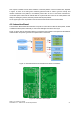
The Sensor&Management Board runs the control loop displayed in Figure 24. To ensure the correct
processing of the loop, a watchdog timer is running and if the system blocks in some part, the system
will force a reset of the board.
The Sensor&Management Board uses two different methods to control the robot:
1. Low-level Control Loop - The loop will check for USART communication problems,
communication losses, check for collision, obstacle detections, manage the power supplies
and finally sample the environment sensors.
2. Interrupt Driven Events - Whenever the Navigation Computer sends a command to the
Sensor&Managment Board an interrupt event is generated. This will allow priority to be given
to the commands from the Navigation Computer. When an interrupt event is activated the
system processing jumps from the low-level control loop to the interrupt routines. When it
finishes processing the interrupt the system processing will be restored to the low-level
control loop.
The following sub-section will explain the way that each of the methods is implemented.
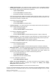
5.1.1 Sensor&Management Low-Level Control Loop
The Sensor&Management Board runs the control loop displayed in Figure 25. To ensure the correct
processing of the loop, a watchdog timer is running and if the system blocks in some part the system
will force a reset of the board.
The cycle starts by checking:
FROG – FP7 STREP nr. 288235
Deliverable: D1.4 – Platform User and Developer Manual 28
Figure 24: Sensor&Management Control Loop and Event Management