
Datasheet


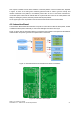


The Interaction Computer will communicate with the Interaction Board using two distinct USB ports.
One port will communicate directly through an USB to RS232 converter with the three Herkulex
motors that control the 3DOF arm. The other USB port will connect to the PIC18F2520 microcontroller
and will be used to send commands to control the green eyes of the FROG Robot, to enable and
disable the Laser pointer and finally to control the intensity of the green LED lights that surround the
laser pointer. Figure 20 depicts the Interaction Board layout.
4.6.1. 3DOF Arm
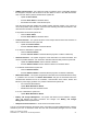
The 3DOF Arm is able to move by the use of three Herculex motors that are placed in each joint of
the arm. The Herculex motors
4
, depicted in Figure 21, are state-of-the-art motors that incorporate
motor, gearbox, control circuitry and communications capability in one single package.
The motors are connected in a daisy chain way and each motors has its own address. The Interaction
Board connects to the base motor by the use of a four-wire cable, then this motor connects to the
second and the second connects to the third motor.
To control each motor the controller has to send the motor address, the position command and the
time that the motor has to perform that operation.
In terms of control algorithm, the motor uses a Proportional-Integral-Derivative (PID) controller with a
trapezoidal velocity profile.
It is able to give the feedback of the position, speed, temperature, load and other internal values.
4.6.2. FROG Eyes
One of the ways that FROG has to interact with people is by the use of the eyes. They will have an
important role in drawing people's attention to look in a certain direction or exposing the robot “mood”.
Each eye will be mounted around one of the stereo Dalsa cameras. The lens of the camera will be
placed in the middle and the lights will show where the robot is looking.
Each eye has 96 independent green LEDs, divided over 3 rows of 32 LEDs. The internal circle has a
diameter of 3.6 cm to allow the camera lens to be mounted and also the lens protection to be fitted.
The external circle has a diameter of 12 cm. The right image of Figure 22 shows the final placement
where the LEDs will be soldered.
Each eye is composed of two boards: the board with the LEDs and a second board with the LED
controller. They are depicted in Figures 22 and 23.
4 http://www.robotshop.com/content/PDF/manual-drs-0101.pdf
FROG – FP7 STREP nr. 288235
Deliverable: D1.4 – Platform User and Developer Manual 26
Figure 21: Herculex Motors