
Datasheet


4.5. Joystick Wireless Controller
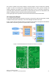
The Joystick Wireless Controller is composed of two different circuit boards (depicted in Figure 17):
• Wireless Joystick Emitter Controller Board - This board is controlled by a PIC18F2520
that reads the information from an Analog Joystick and converts it to command references
that are sent to the FROG robot platform. An Enable push button and an Emergency button
are also connected to the board, allowing the user to take control of the platform or send a
Stop Emergency command to the platform. To transmit the data, a Wireless 19200 bits of
baud connection is used. For that purpose an ERA900TS wireless emitter has been installed.
The wireless Joystick system is powered by 4xAAA rechargeable batteries, and an external
plug allows the system to be recharged, without having the need to open the controller and
remove the batteries.
• Wireless Receiver Controller Board - This board is controlled by a PIC18F2431 that
receives the wireless data transmission from the Wireless Joystick Emitter Controller,
processes the received data and sends control commands to the Motor Board. To receive
the data the system uses an ERA900TRS transducer. The board uses 2 different ways to
send and alert the Motor Board of the existence of Joystick commands. Two digital ports
indicate if the Joystick is taking control or if the Emergency button has been pressed. If the
Joystick is taking control then the Motor board will use the I2C port to get information about
the values to send as motor references.
FROG – FP7 STREP nr. 288235
Deliverable: D1.4 – Platform User and Developer Manual 24
Figure 17: Wireless Joystick Emitter (left) an Receiver (right) Controller Boards
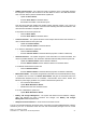
Figure 18: Wireless Joystick Emitter command