
Datasheet


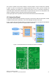


The mechanics to guide the robot to dock and the Docking Station are being produced. Figure 14
shows the current design of the Docking Station. From the image it is possible to see the Docking
Station’s three main features:
1. The Docking Station guiding shape. The V-U design is about 5 cm high and will
mechanically guide the robot to the power bar. This design has been tested with the real robot
allowing the perfect end alignment, even when the robot enters the docking station with a high
rotation error.
2. The two guiding colour marks. This will allow the robot to adjust its position to the Docking
Station, the robot system will be able to measure the distance to the Docking Station, by
calculating the relation between the real size of the colour marks and the size of the image
and also will be able to adjust it’s position by trying to centre the common edge of the two
colours in the centre of the image.
3. The long and wide power bars. They will provide enough surface area to provide all the
power that the robot needs to charge the batteries and power all the components.
The following figures depict the robot in Docking Station. Figure 15 shows the robot aligned and
parked in the station. Figure 16a) shows the two contact springs of the FROG robot connecting to the
power bars of the docking station. One of the bars is the negative pole and the other is the positive
pole of the 18V charger power supply. Figure 16b) shows a zoom image of the contact between the
power springs of the robot and the power bar of the Docking Station.
FROG – FP7 STREP nr. 288235
Deliverable: D1.4 – Platform User and Developer Manual 23
Figure 15: FROG Robot in the Docking Station
Figure 16: a) robot connecting to Docking Station; b) detail of the robot contact spring