
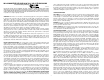
User Guide

Red
Black
White
Main Board
White
Black
Red
Engine Board
M
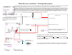
#566 SPST switch.
Switch shown in the OFF position.
Left Rail pickup Black —› Yellow
Motor Brown —› White
Motor Blue —› Red
Right Rail pickup Black —› Blue
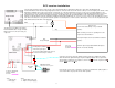
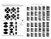
Aristocraft Power Truck wire pickup help guide.
Terminal connection wire color receiver color
Lef t / right rail will reverse in the opposite pickup
truck. This drawing was made from their SD45.
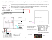
7
The white wire from CONN1 on the Engine
Board and Main Board do not get connected.
Either remove from connector housing, cut,
or tape end.
Black
Aristocraft Radio Receiver
receiver motor leads
Track power input to receiver
connect function outputs to appropriate Main Board
inputs as shown on lower left of drawing.
The batt jumper (outlined in
RED)
should not be put in place.
F1 F2 F3 F4
cable to
ART-5490
as shown
ON / OFF switch
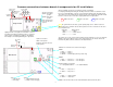
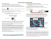
Connect all wires between boards as shown on page 3. Place the Engine Board in an appropriate location in the engine. Place the Main Board and
Volume/Treble/Bass board in the tender body at appropriate locations. Also place the Aristocraft radio receiver boards in their appropriate locations or where space
permits. Be careful, as always not to short anything to the boards or wires.
The headlight, marker lights, and cab lights will operate automatically with the sound system or you can choose to utilize the lighting from the Aristocraft receiver.
Whenever motor power is detected, the cab light will turn off and the appropriate headlight and marker lights will illuminate. So, you have your choice, either
operate them with the receiver or leave them connected to the sound system for automatic operation. The flickering fire box, if desired, can be either lamps in
series or a 5 volt lamp painted red. Light bulbs will function better than LED's in this application.
fixed track power
input - AC or DC
If you want the sound system on at all times,
connect the on/off switch wires (SW1) together.
Connections as shown:
Sound Function Relay/Keypad
F1 - Whistle ......................... A
F2 - Bell ................................ C
F3 - Cylinder Blow Down ...... D
F4 - Simple/Compound ........ E
you may elect to connect all, some, or none.
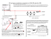
Track Power.
Input voltage of 12 to 24 volts DC or AC.
This voltage must be permitted by the
track operated receiver as well.
Connect to the track input from each truck.
If this is an Aristocraft receiver in a
non-equipped plug in, then connect to the
same wires as the receiver board (wire #1
& #7, blue & yellow)
Aristocraft relay board
(ART-5490)
Cable plugs into
receiver board
Aristocraft/Crest #CRE-55492 receiver installation using fixed track power and Aristocraft relay board (ART-5490)
for sound function operation.
different colors
utilized for easier
wiring/viewing.
White