
User Guide

5
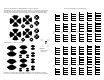
DCC receiver installation
Red
Black
White
Main Board
White
Black
Red
Engine Board
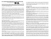
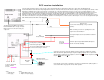
Connect all wires between boards as shown on page 3. Place the Engine Board in an appropriate location in the engine. Place the Main Board and
Volume/Treble/Bass board in the tender body at appropriate locations as well as the DCC decoder. Be careful, as always not to short anything to the boards or wires.
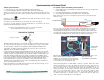
Regulated 5 volt lighting can be either connected to the sound boards or to a function output from the decoder. You can use the 5 volt lamps with their + lead
connected to the red +5 volt regulated output from the sound card and then connect the other end of the light bulb (or LED with appropriate limiting resistor) to the
appropriate function on the decoder. The headlight, marker lights, and cab lights will operate automatically with the sound system. Whenever motor power is
detected, the cab light will turn off and the appropriate headlight and marker lights will illuminate. So, you have your choice, either operate them with the decoder or
leave them connected to the sound system for automatic operation. The flickering fire box, if desired, can be either lamps in series or a 5 volt lamp painted red. Light
bulbs will function better than LED's in this application.
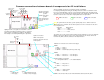
The white wire from CONN1 on the Engine
Board and Main Board do not get connected.
Either remove from connector housing, cut,
or tape end.
Black
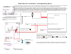
DCC Receiver
receiver motor leads (Orange / Gray is standard
practice).
Make sure that your receiver is operating in the same
step mode as the transmitter !!
Track power input to decoder (Red / Black is standard
practice).
Function outputs to appropriate Main Board inputs as
shown on lower left of drawing.
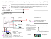
Gray
dccF2
1 - Cylinder Blow Down (red)
2 - Simple / Compound (gray)
dccF1
1 - Whistle (red)
2 - Bell (gray)
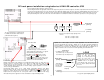
The batt jumper (outlined in RED)
should not be put in place.
M
Some DCC systems may require the addition of another capacitor to stabilize the regulator
which will show in the lights flickering (if using the 5v lighting supplied). If this is experienced,
add a 470mfd to 1000mfd, 25 volt, capacitor as shown. The
RED side of the capacitor is the "+"
lead, the
GRAY wire is the "-" lead.
+
#566 SPST switch.
Switch shown in the OFF position.
If you want the sound system on at all times, connect the on/off switch wires (SW1) together or
use a function with a relay to provide remote switch operation.
F1 F2 F3 F4
Connect to appropriate
functions from the
decoder.
do not connect batt red wire! Tape end, cut,
or remove from housing of connector.
To F1, F2,
F3, and F4
as shown
ON / OFF
switch
DCC
track power input
White