
User Guide
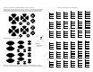

Main Board
Engine Board
4
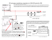
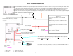
DC track power installation using batteries & DALLEE controller #755
*Larger motors require a larger capacity choke.
Chokes:
Item 702 - 1.5 ampere loads
Item 703 - 5.0 ampere loads
Left Rail
pickup
Right Rail
pickup
CHOKE *
White
Battery power: When using standard, non-rechargeable, battery power you must make sure
that the jumper is removed (located to the right of the "batt" label and shown in
RED
above) must not exceed 24 volts DC. Use a string of 6 or more AA or AAA batteries (24
volt DC maximum input). Life depends on volume settings. Typical operation is in excess of
12 hours using good AA batteries.
Rechargeable battery power: use 6, 1.2volt 700ma, rechargeable batteries (item #648).
Place the jumper onto the selector located above and highlighted in
RED. This will allow the
batteries to charge whenever the track voltage is higher than the battery voltage. The
batteries will also charge when the sound system "SW1" is in the off position. Full charge
will result when power is applied for 14 hours. Item #652 is a 6 pack AA battery holder.
White
Black
Red
CHOKE PACK
for additional chokes order:
Item 702 for up to 1.5 ampere load
Item 703 for up to 5.0 ampere load
LOAD
Formerly right
rail pickup
CHOKE
looks like coil of wire with a
lead on each end
either rail may
be used. Right /
Left only used
for reference.
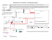
Lighted car / other engines used in consist preparation. You will know if this is
necessary by placing the locomotive / lighted cars on the track and then attempting to
blow the Whistle or operate the BELL. If they do not operate with the other items on
the track then you need to do the following. We suggest doing this to all lighted cars or
engines used in the same consist since it lets the signal stay at it's maximum level.
Lighting load, other locomotive in
consist, or other type circuitry
drawing off of track power. As
shown one lead needs to be
disconnected from the rail and a
"CHOKE" needs to be placed in
series with the load. In most cases
the 1.5 ampere (#702) will handle
the load.
Left Rail
Pickup
Right Rail
pickup
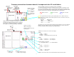
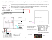
Connect all wires between boards as shown on page 3.
Place the Engine Board in an appropriate location in the engine. Also place the choke in the engine as shown. It is important to make all of the previous
connections from the right rail to move to the side after the choke. While the drawing shows the motor, previously installed lighting, and a smoke unit, your
engine may not contain all of them. You may also wish to change the factory installed lighting to that supplied from the sound cards. Failure to connect
other power drawing items to the other side of the choke will result in the LocoMatic™ Controller to not be able to operate the sound system properly.
DC
motor
Smoke
Unit
Red
Black
White
White
Gray
ON / OFF switch
#566 SPST switch.
Switch shown in the OFF position.
lighting
circuits
as explained on page 3, connected on/off
switch to SW1 red and gray wires (see pg6 for
a better drawing of this connection).
batt: Make sure the
RED wire goes to the
battery
"+" and the GRAY wire goes to the
battery
"-". Failure to do so may create severe
damage to the board as well as the batteries
and is not covered under warranty!
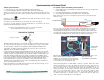
See pg 8 for optional lighting boards.
The Aux Tender lamp is controlled via the
LocoMatic™ Controller's "Aux2" function
(Cntrl-Aux buttons together).