
User Guide
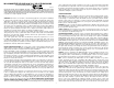

Engine Board
Main Board
3
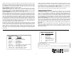
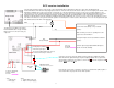
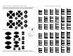
Definitions of connections to be shown on later pages:
CONN1:
1 - RED ............. Motor 1
2 - BLACK ......... Motor 2
3 - WHITE ......... track RF input (for DC operators only)
CONN2:
1 - RED ............. DCC rail 1 .......... also AC input 1
2 - GRAY ........... DCC rail 2 .......... also AC input 2
unlabeled, battery select jumper:
on - rechargeable batteries ......... off - standard batteries
batt:
1 - RED ............. DC power "+"
2 - GRAY ........... DC power "–"
SW1:
1 - RED ............. switch common
2 - GRAY ........... switch open
CONN3 - this connector mates to the Volume/Treble/Bass board (not shown) cable.
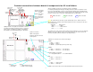
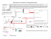
All of the following connections are required for any type of installation.
For simplicity in drawing and viewing, the following connections, which are outlined in colored
boxes for easier identification, need to be connected from the Main board to the Engine board.
The red wire goes to the mating red wire and the gray wire to the mating gray wire between both
boards. Do not reverse the colors and do not plug them into the wrong locations.
PWR connections AUD connections SYNC connections
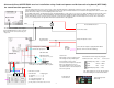
The yellow framed connections go to the optical pickup sensors. SYNC1 is the front
drivers optical sensor, SYNC2 is the rear drivers optical sensor. The connections are the same
for each optical sensor.
SYNC wire Optical Sensor
White ......................... White
Black ......................... Black & Green
Red ............................ Red
The optical sensor needs to be mounted so that the front focal distance is 1/8" to 1/4" maximum.
With the sound system "ON", the optics can be easily aligned since an exhaust chuff can be
heard from any white (reflection) to black (no reflection) transistion.
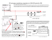
Common connections between boards & components for All installations.
Speaker connections:
SPKR1 - Front driver
speaker
SPKR2 - Rear driver
speaker
Each red & gray wire
pair connect to each
speaker.
Speaker connections:
SPKR - main speaker
Red & gray wire pair connect to
tender speaker.
White
Black
Red
White
Black
Red
Gray
Red
Gray
Red
Gray
Red
White
Black
Red
W
B
R
Gray
Red
Gray
Red
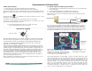
100 ohms
Marker Lamps
#384 (1.5v)
Headlight
#756 (5v)
Firebox #384
(3 in series)
Cab
#756
Gray
Red
Red
Black
White
G
R
G
R
G
R
G
R
G
R
G
R
G
R
White
Black
Red
Aux. Tender
#756
Backup light
#756 (5v)
G
R
G
R
Lighting: Red wire is a regulated +5 volts which is common
to all lamps. All outputs are pulled to ground ("-") to turn the
lamps or LED's on. Outputs are capable of 120 milliamps.
Exceeding the current rating will damage the output driver.
dccF2
1 - Cylinder Blow Down (red)
2 - Simple / Compound (gray)
dccF1
1 - Whistle (red)
2 - Bell (gray)