
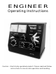
User Guide

matching of throttle pulse output to
the starting characteristics of the
motors in the various types of your
locomotives. Rotating this control
clockwise increases pulse height.
Pulse frequency is automatically
varied according to demand
established by throttle output voltage.
With the PULSE control in full
counter-clockwise position the pulse
circuit is off.
Below the reversing switch is the
throttle SPEED control which
determines the output voltage to the
track and consequently locomotive
speed. While clockwise rotation
increases speed, it may be more
convenient to set this control at a
maximum speed setting and use the
brake switch for actual operation.
IMPORTANT--- There is no "OFF"
position on the speed control. Full
counter-clockwise results only in a
minimum output which can allow
locomotives to creep. To bring a
locomotive to a complete stop the
BRAKE switch must be used.
To the right of the SPEED control and
centered on the lower row of controls
is the THROTTLE RESPONSE or
"momentum" control. This control
adjusts the time frame required for
output voltage to change from one
speed setting to another. Clockwise
rotation increases the time frame and
therefore longer delay (slower
response). The right side of the panel
is devoted to the braking system and
contains two controls. The upper
control is the actual BRAKE switch
which, with its four positions, is the
heart of the ENGINEER's operating
functions. These four positions are
labeled RELEASE, LAP, SERVICE, and
EMERGENCY. With the BRAKE switch
in RELEASE the SPEED control and
its momentum adjustment, also the
pulse generation circuitry, are
connected to the CAB output and the
train will accelerate to whatever
speed is set on the SPEED control.
The LAP position is similar to a cruise
mode where the train will maintain the
speed at which LAP was selected.
SERVICE is an actual braking
application. When SERVICE is
selected, the output voltage to the
track is reduced, which causes the
train to slow down to an ultimate stop.
The rate at which this slow down
occurs is varied by the BRAKE
RESPONSE control. The
EMERGENCY position provides a rapid
stop. The BRAKE RESPONSE control
located directly below the BRAKE
switch is an additional momentum
adjustment which varies the
deceleration available during a service
brake application. Clockwise rotation
of this control increases the response
time of the braking application, taking
longer to slow down and thereby
simulating a heavier train. It is also
possible to "LAP" the brakes by
alternating the brake switch between
the SERVICE and LAP positions. This
will simulate the action of an "air" train
brake.
THROTTLE OPERATION
Now that you are familiar with the
location and function of the various
components and controls of your
ENGINEER, lets hook up to the layout
and practice running a locomotive.
Connect the CAB output terminals on
the back of the ENGINEER to the
track using your existing power
distribution system. We recommend
the use of #16 gauge or heavier wire,
depending on the size of your layout
and the length of the wire runs out to
the track. A simple rule to follow: the
longer the wire and the larger the
load(current draw), the heavier the wire
should be to minimize line loss(voltage
drop) between the throttle and the
track. It may be advisable to use wire
as large as #8 or #10 to get the full
use of the high current capabilities of
your ENGINEER.
Put the BRAKE switch in
3