
User Guide

OVERVIEW
The ENGINEER THROTTLE is an
integrated circuit design, full feature,
momentum throttle. The standard
ENGINEER produces 13 volts DC with
a maximum current of 5.0 amperes.
The GAUGE-1 ENGINEER produces
18 volts DC with a maximum current
of 4.0 amperes. In addition to its meter
instrumentation and adjustable pulse
generation circuitry, the ENGINEER
allows the user to vary both the
throttle speed response (momentum)
and the service brake response. This
variability of both throttle and brake
response permits realistic simulation
of handling characteristics ranging
from light engine movement to full
tonnage trains. Interlocked reverse is
also a standard feature of the
ENGINEER. Interlocked reverse
requires the train to stop before the
reverse switch becomes functional.
The ENGINEER is equipped with a
regulation circuit which maintains a
constant output voltage and therefore
constant locomotive speed. The
ENGINEER's pulse generation circuitry
allows adjustment of pulse height to
permit matching of pulses to individual
locomotive motor starting
requirements. The pulse frequency is
varied automatically according to the
demand established by the
ENGINEER's output voltage level.
The ENGINEER has a four position
brake switch which simulates most
operating functions including
acceleration, deceleration and/or
braking and continuous running. This
brake switch, together with the
reverse interlock feature are
combined in the optional
WALK-A-ROUND controller to permit
walk around control, with memory, of
the ENGINEER from any number of
remote plug in locations.
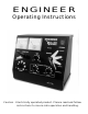
DESCRIPTION AND LOCATION OF
COMPONENTS AND CONTROLS
On the rear face of the ENGINEER
you will find the power cord, a
resettable circuit breaker and a
barrier strip with two terminals. These
two terminals are for the output to the
track. There are no other outputs
provided as it is our judgement that all
power in the throttle should be
reserved for output to the track and
any accessories should be connected
to a separate power source.
The voltmeter is located in the upper
left area of the face panel and is used
to monitor track voltage. Adjacent to
the voltmeter and to its right is the
ammeter which is used to monitor the
current flow to the track (load). To the
right of the meters you will find a red
indicator which is used to show
maximum current conditions. During
short circuit or currents in excess of
maximum, this indicator will illuminate.
If the overload continues the ampere
output will become less than when the
short/overload occurred (this is known
as foldback current limiting) and the
output voltage will gradually decrease
to a low setting. This will eliminate
jack rabbit starts which would
otherwise occur when the overload is
corrected.These indications depict
proper function of the internal,
electronically limiting, output current
regulator.
In the upper right corner is the power
switch which will glow green when the
ENGINEER is "ON".
Below the meters, at the left, is the
reversing switch. This switch is like a
DPDT type without center off. Its two
positions are labeled FORWARD and
REVERSE and its function is
interlocked so that direction can only
be changed when throttle output is at
zero voltage, indicating a full stop.
To the right of the reversing switch
and at about the center of the panel is
the PULSE control which allows the
2