
User Guide
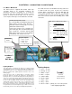

installation - connections to main board
7
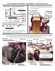
Lighting Outputs:
each output shown, as described in the main text, is capable of driving
one 60 milliamp load. This load may be a light bulb, as supplied, LED's
(with limiting resistor), or a series of light bulbs. Item #756 contains more
lamps as provided. More detailed optional connections exist on the
following pages.
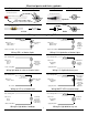
Connect the proper wires to supplied lamps as described. Insulate
properly. As with any connections, an improperly or uninsulated wire
touching the frame or other wire will damage the unit! Any damage as
such is not covered under warranty. When connecting the lamps to the
common +5v power, split the load between the two wires (red & orange).
Use one for the front lights and the other for the rear lights. If any
switched lamp output no longer operates, this is a sign that the output
was either overloaded or came in contact with another wire. A short
between wires to the lamp is also a overload. This would indicate a need
for repair and has to be returned. Again, this type of failure is not covered
under warranty since it is due to improper handling during installation.
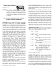
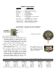
LocoMatic™ Main Board
The main board is supplied with double sided tape
especially made to be electrically insulated, non
absorbent to moisture, anti-fungal, etc.. To mount the
board find and clean (possibly with alcohol to remove
grease) a location. Peel the tape cover off. Press to
secure in place. More tape can be obtained as item 388.
Lighting Outputs
1 .... Red ....... +5 volts
2 .... Orange .. +5 volts
3 .... White ..... Lmp F
4 .... Blue ....... Lmp R
5 .... Yellow .... Mkr F
6 .... Brown .... Mkr R
7 .... Violet ..... Aux 1
8 .... Gray ...... Aux 2
9 .... Green .... Cab 2 ..... primary use is for rooftop strobe
or mars lightingif applicable.
LocoMatic™
type 3
Main Board
.Item # 756
5 Volt, 60 milliamp
high intensity lamp.
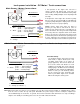
Main Power / Motor Connections
Motor Brushes
1 ....... Red
2 ....... Brown
Track Power Input
3 ....... Blue 3rail - center roller pu
2rail - left rail pickup
4 ....... Black 3rail - chassis pickup
2rail - right rail pickup
Motor Field Wires
5 ....... Yellow
6 ....... Orange
The small connectors are handled better using a tweezers
or small needle nose pliers to place the connectors
together. When seperating the connectors DO NOT pull
on the wires! Instead, slide a tweezers (or small flat
screwdriver between the top connectors lip and the board
mate. Care must be taken when handling these small
connectors.
Auxillary Backup Battery input
Use only item #647 rechargeable battery! Item
#578 contains connector snaps with wires.
Item #579 contains mounting clips or use Item
#388 double sided foam tape.
Connect the red wire to the red battery clip
wire and the gray wire to the black battery clip
wire. Insulate the connection properly. DO
NOT get these wires reversed, severe damage
to the battery / unit / and you can occur!
Speaker
connection
Coupler Outputs
1 .... Red ..... +5 volts
2 .... Black .... Front
3 .... White ... Rear
for use with item#501 only!
SYNC input
not used with
Diesel sound
systems
to Sw/vol-h
board