724 Robbins Road Grand Haven, Michigan 49417 616-842-7110 Phone 800-937-3253 616-842-0859 Fax 800-846-3253 Web: www.dakecorp.com E-mail : customerservice@dakecorp.com technicalsupport@dakecorp.
Section I INTRODUCTION 1. This manual has been created by DAKE to give the Customer all the necessary information for regular use and correct maintenance of the hydraulic presses in the DURA PRESS series. It contains the use and maintenance instructions as well as the safety and calibrating instructions requiring your direct action. 2. It is advised to keep this publication in a good condition and somewhere easily accessible to enable rapid reference in case of need or work. 3.
Section II LIST OF SAFETY CHECKS ALWAYS ACT WITH CAUTION ATTENTION PRECAUTION Read the rest of this section very carefully before proceeding to read the following sections. CAUTION general When working always pay attention and be alert. Be careful. Be aware of possible hazards. CAUTION regulations Observe the law and regulations of the premises regarding you and your machine. CAUTION clothing Injury may occur if you do not wear suitable clothing. Loose clothing may get caught up in the machinery.
CAUTION pressure pipes The flexible or metal pipes of a system may hold fluids under pressure even with the system switched off. Before dismantling them, check on the diagram whether the section could be under pressure. In any case, loosen the fittings slowly. CAUTION hydraulic oil Very fine jets of high-pressure hydraulic oil can penetrate the skin: do not use your fingers to detect any leaks of hydraulic oil, neither put your face close to them, but use a piece of cardboard to check for any leaks on them.
Section III TABLE OF CONTENTS SECTION I INTRODUCTION SECTION II LIST OF SAFETY CHECKS SECTION III TABLE OF CONTENTS SECTION 1.0 1.1 1.2 1.3 1.4 1.5 1.6 GENERAL SAFETY INSTRUCTIONS General instructions and definitions Description Use Press identification Safety labels General safety instructions SECTION 2.0 2.1 2.2 TECHNICAL DATA SHEET Cylinder and spare parts section Manual pump and spare parts section SECTION 3.0 3.1 UNPACKING Disposing of the packing SECTION 4.0 4.1 4.
Section 1.0 1.1 GENERAL INSTRUCTIONS AND DEFINITIONS This handbook is an integral part of the product; IT MUST be carefully conserved for future reference. FOR ANY REQUEST FOR CLARIFICATION, ASK YOUR EMPLOYER OR THE DAKE TECHNICAL SERVICE, AVOIDING ANY PERSONAL INITIATIVE THAT COULD CAUSE VERY SERIOUS OR FATAL ACCIDENTS. Before using the machine, read the warranty carefully.
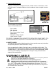
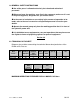
1.4 PRESS IDENTIFICATION The press is fitted with a rating plate fixed in a visible manner on the rear as shown in Fig. 01 below. Dake part number and serial number on front name plate shown in Fig. 03 Fig. 03A Part No. 607 The rating plate (Fig. 02/03A) shows the identification data: MODEL TON MAX PRESSURE MAX SERIAL NO.DAKE Press model Max. tonnage Max. pressure Press serial number/ Year of Manufacture - Dake part number (Tag 03) - Serial number (Tag 03) - PSS 20 200 023.98 Fig.
Label 300168 Label 84487 Label 84399 Label Placement View 81002 300168 607 84487 Label 607 84399 Force 10M /Force 20M8 8 06/10
1.6 GENERAL SAFETY INSTRUCTIONS Use of the press is allowed exclusively for trained and authorized personnel. When you leave the machine, even if only for a moment, make sure it is not in the pressing phase, dangerous for you and for others. In the event of confusion or uncertainty in the manner of operation to be made, refer to the user’s manual or call qualified personnel to resolve your doubts. Operate the manual pump only from the working position that is in front of the hydraulic power unit.
2.
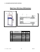
Model Force 10M & Force 20M Breakdown Hand Pump Assembly Item No Part Number Force 10M Force 20M 302367 302367 302368 302368 302369 302369 302370 302370 N/A N/A 302373 302373 302372 302346 302371 302371 N/A N/A 300366 301485 301327 301542 301575 301574 301576 --301573 Description 12 Piston Pump 2 Handwheel 20:29 Valve 31-32-33 Valve 30 Filter 34 Rod assembly 6 Spring 5 Cap 25 Tap Screw Complete Pump Gasket Repair Kit Linkage Assembly (Item 9,10,11,15,16,34) Relief Valve (Item 1,2,3,4,5) Relief Valve 4NV
3.0 UNPACKING If the machine is supplied wrapped in plastic sheet, any accessories, spare parts and expendables are packed in cardboard boxes and positioned on top of the worktable. To remove the packing, cut the plastic wrap, taking care not to damage the machine or cardboard box. Remove any accessories from on top of the worktable, check the contents correspond to the order and to the accompanying documentation. After removing the plastic, unbolt the lag bolts from the skid.
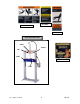
Section 4.0 4.0 HANDLING, TRANSPORT AND POSITIONING For handling the packed machine, as described above (see section 3.0), it is necessary to use special lifting equipment whose maximum lifting capacity must be no lower than the total weight of the press. THE TOTAL WEIGHT OF THE PRESS PLUS PACKING IS SHOWN ON THE ADHESIVE TABS PLACED ON THE PACKING AND ON THE ACCOMPANYING DOCUMENTS. For loading and unloading the machine, lifting straps are to be used positioned as shown in Fig. 04. 4.
4.2 POSITIONING THE PRESS Simple precautions are necessary for correctly positioning the press. Always consider the safety aspect not only in relation to the work carried out with the press, but also to the dangers originated by the other machines in the workplace.
Section 5.0 5.0 COMMISSIONING AND STARTING This section describes the operations to be followed on commissioning along with some advice for starting the machine for the first time. 5.1 FILLING THE PRESS WITH OIL To fill the press, use exclusively the oils indicated in the table or ones of equivalent reliability. The choice must be made considering the environmental conditions and the operating features of the press.
5.3 AIR DISCHARGE After the first start-up, or after maintenance carried out on elements of the system (e.g. cylinders, filters, pipes, changing oil) a considerable quantity of air may be present in the circuit. Irregular operation, noise, and/or uneven cylinder movement highlight the presence of air. It is necessary to discharge the air as follows: - Pump ram down to the maximum stroke. - Loosen the upper nipple of the press cylinder and wrap it in a cloth to avoid oil splashes.
Section 6.0 6.0 SAFETY INSTRUCTIONS THE MANUFACTURER DECLINES ALL LIABILITY FOR DAMAGE TO THINGS OR PERSONS CAUSED BY NONOBSERVANCE OF THE SAFETY INSTRUCTIONS GIVEN IN THIS MANUAL WHICH SUPPLEMENT THE CURRENT LEGAL REGULATIONS IN WORKPLACES. IT IS EXTREMELY IMPORTANT FOR THE OPERATOR TO UNDERSTAND ALL THE SAFETY INSTRUCTIONS LISTED BELOW IN ORDER TO PREVENT DAMAGE TO THEMSELVES, TO THINGS OR TO OTHERS.
Section 7.0 7.0 OPERATION Before starting any operations, make sure there are no other persons in the immediate vicinity of the machine. IT IS STRICTLY FORBIDDEN TO PASS UNDER THE WORK TABLE. 7.1 CONTROLS To make the press work you have to stroke the pump control lever. The feed speed of the cylinder and the pressure will depend on the driving speed of the pump control lever.
Section 8.0 8.0 MAINTENANCE AUTHORIZED AND TRAINED PERSONNEL MUST CARRY OUT ROUTINE MAINTENANCE OPERATIONS. ALL MAINTENANCE OR CLEANING OPERATIONS MUST BE DONE WITH THE MASTER SWITCH OFF. (IF EQUIPPED) SPECIAL MAINTENANCE OPERATIONS (REPAIRS) MUST BE CARRIED OUT BY THE MANUFACTURER’S PERSONNEL ON THE PREMISES OF THE MANUFACTURER OR BY SUITABLY TRAINED AND SPECIALIZED PERSONNEL UPON AUTHORIZATION BY THE MANUFACTURER.
8.3 CLEANING CARRY OUT THE CLEANING OPERATIONS EVERY WEEK. It is a good rule to carry out periodical cleaning of the press in order to eliminate foreign bodies (e.g. dust, extraneous and dirty substances, etc.). Eliminate all foreign bodies from the piston rod that could damage both the surface of the rod and the cylinder gaskets. While cleaning, use detergent substances that are not harmful, do not pollute and are in conformity with the law.
Section 10.0 10.0 PUTTING OUT OF SERVICE In the case of putting away for a long period it is necessary to empty the unit of oil and protect it suitably so there is no dust, moisture, or other foreign bodies, exposed to the unit that can damage the parts of the unit. When putting into operation after a period of storage, meticulously follow ALL the indications of Section 5.0. Section 11.0 11.
Gauge Conversion 10 ton Bore 60 mm = 2.362” 10 Ton 5 Ton 4 Ton 3 Ton 2 Ton 1 Ton 302 bar 151 bar 121 bar 90 bar 60 bar 30 bar 4565 PSI 2282 PSI 1825 PSI 1369 PSI 913 PSI 456 PSI Gauge Conversion 20 ton Bore 80 mm = 3.