
User manual


Configuration Procedure
1.
Mounting
For safety reasons, please disconnect ESCs and Power Connection Adapter or remove
all propellers during configuration and system setup!
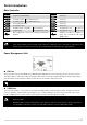
STEP1: IMU Orientation
Select IMU mounting orientation. Orient the IMU such that
the arrow marked on the printed surface of the IMU faces
the sky and points directly forward, backward, left or right.
The sides of the IMU should be precisely parallel to the
multi rotor body.
DO NOT MOUNT THE IMU UPSIDE-DOWN.
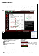
STEP2: Mounting Location
Install all payloads that will be used during the flight,
including batteries, camera mount and camera. Balance
the multi rotor as you would normally, with the center of
gravity (C.G.) directly on the center plate. Fill in the
distance between body center of IMU/GPS and the C.G.
of multi rotor in X, Y & Z axles as showed in the figure.
1
You must re-configure if the ALL-UP-WEIGHT had
been changed on your multi rotor,
2
If mounting locations are not accurate enough or
the sign were wrong, error on X, Y,Z axles will
leads the oscillation of your multi rotor.
3
Make sure to follow the diagram in Assistant
software: red is positive, green is negative; unit of
measure is CM, NOT INCH.
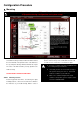
Step 1
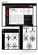
Step 2