
User manual


Mounting and Connection
Note: Failure to follow any guidance outlined in this page will have severe consequence of your multi-rotor flight characteristic or worst crashing your multi-rotor or bodily harm.
IMU
Main Controller:
· There is no orientation requirement for the Main Controller. Choose a
mounting location where as shorter ESC extension wires are needed as
possible. Please make sure all ports are accessible when installing the MC so
as to facilitate wiring and software configuration.
· In three-pin ports, pins near the nicks are signal pins.
After choosing a location to mount the MC, it is recommended that you DO
NOT mount the MC until all wirings and software configurations are completed.
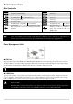
LED Indicator:
Place the LED indicator at an appropriate
location of craft body far away from the
GPS. Do not mount it on other electronic
devices. Make sure You can see the light
during the flight. You can connect LED to
one of the two ports as figure shows.
To ESCs
GPS
LED
GPS/COMPASS (with Bracket):
· GPS/Compass is sensitive to magnetic interference, should be far away from any electronic devices.
· You should use epoxy resin AB glue to assemble the GPS bracket first as the figure showed in previous page.
· Mount the bracket on the center plate of craft first, then fix the GPS on the plate of the bracket (by 3M glue
provided). The GPS is sensitive to vibration interference, so position the bracket at least 10 cm from any rotor.
· The DJI logo marked on the GPS should face the sky, with the orientation arrow pointing directly forward. The
GPS/Compass is packaged with a special indication line for mounting for the first time.
If you are uncertain whether materials near the GPS/Compass module are magnetic or not, you can use a
compass or magnet to check it. If you use your own mounting rod, make sure it is NOT magnetic!
IMU:
· The IMU is best positioned near the multi rotor’s center of
gravity, where vibration is relatively low.
· Orient the IMU such that the arrow marked on the p r i n t e d
surface of the IMU faces the sky and points directly forward,
backward, left or right.
· The sides of the IMU should be precisely parallel to the multi
rotor body. Use double-sided foam tape for secured installation.
· Check the double faced adhesive tape regularly to ensure that
the IMU is securely positioned.
· DO NOT cover the ventilation holes, keep them unobstructed.
· The IMU module is NOT water-proof or oil-proof.
· Do not mount the IMU upside-down.
R/C Receiver
(Futaba / Hitec)
1
2
3
4
7
R/C Receiver
(JR)
AUX2
AUX1
GEAR
RUDD
RUDD
THRO
AILE
ELEV
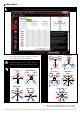
ESC & Motor:
· Please make sure you are using the ESCs and motors recommended by the manufacturer of
your multi rotor first. Supported ESC output by WKM is 400Hz refresh frequency. We
recommend the use of external switching type BEC of 5A or higher for all AP work and larger
than 650 size multi-rotor, and cut the red wire of ESCs with built-in BEC.
· Connect ESCs to motors, then calibrate all your ESCs one by one through the receiver directly
before connect them to your MC, Make sure program all of them into Governor off, Break off and
Normal Start up to get best experience.
· Connect all ESCs to MC by the motor numbering method introduced in our Assistant software.
· Cut the red wire (power wire) of your ESCs , the power from V-SEN on PMU is suitable to most
of receivers and other electronic devices. If you want to use other BEC to drive these devices,
you’d better use a 3-pin servo cable without red wire to connect V-SEN to X1. We recommend
the former connection, which can protect your motors and ESCs.
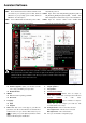
R/C System:
These are example connections.
Please setup Aileron, Elevator,
Throttle, Rudder channels on your
Tx first, and choose one 2 or 3
positions switch/channel as control
mode switch, then connect your
receiver to the right ports on MC.
TX
To ESCs
/
Gimbal
MC
E
T
R
U
X
1
X
2
X
3
A
M
6
M
5
M
4
M
3
M
2
M
1
F
2
F
1
AUX2
Futaba S-Bus
S-Bus
Battery
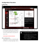
PMU & Battery:
· There is no requirement for PMU mounting.
· Use our Power Connection Adapter (red
line depicts in figure) to connect battery,
PMU and ESCs.
· For safety reason, please disconnect ESCs
and Power Connection Adapter during the
configuration procedure.
· You can choose 2S - 6S LiPo battery.
V-SEN
PW
+
_
PMU
ESCs
……
Tow same ports, can exchange
the connection to ease the wiring.