
User manual


25 |
()
()
( )
3
Also proportion of coefficients of the motors at the same side of pitch axis should be equal to the proportion of force arms of those
motors:
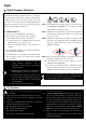
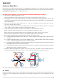
. As we defined before: Pull stick E<0 multi-rotor moves backward; Push stuck E>0,
multi-rotor moves forward, we can choose the following setup:
Hex-rotor V
-100%-100%
0%
100% 100%
0%
Front
M1M2
M3
M4 M5
M6
Roll Axis
Pitch Axis
Yaw Axis
d
2d
a
a
Now if push the pitch stick, the sum of M1, M2 output (C
E1
+ C
E2
) ×E is negative, the sum of M4, M5 output (C
E4
+ C
E5
) ×E is positive,
then multi-rotor moves forward; if pull the pitch stick, the sum of M1, M2 output (C
E1
+ C
E2
) ×E is positive, the sum of M4, M5 output
(C
E4
+ C
E5
) ×E is negative, then multi-rotor moves backward. And the balance along all the other axes can be derived by substituting
the pitch stick command into equations set 3.
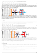
Roll
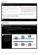
The theory of movement about the roll axis is the same with pitch axis. However there is no motor on the axis in this case, no
coefficient is 0%. We also want multi-rotor to keep balance along all the other axes when apply the roll stick command:
( )
()
( )
4
Also proportion of coefficients of the motors at the same side of roll axis should be equal to the proportion of force arms of those
motors:
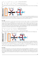
. As we defined before: Stick left A<0, multi-rotor moves left; Stick right A>0
multi-rotor moves right, we can choose the following setup:
Hex-rotor V
-50%50%
100%
50%
-50%
-100%
Front
M1M2
M3
M4 M5
M6
Roll Axis
Pitch Axis
Yaw Axis
d
2d
a
a
Now if move the roll stick right, the sum of M2, M3, M4 output (C
A2
+ C
A4
+ 2C
A3
) ×A is positive, the sum of M1, M5, M6 output (C
A1
+
C
A5
+ 2C
A6
) ×A is negative, then multi-rotor moves right; if move the roll stick left, the sum of M2, M3, M4 output (C
A2
+ C
A4
+ 2C
A3
) ×A
is negative, the sum of M1, M5, M6 output (C
A1
+ C
A5
+ 2C
A6
) ×A is positive, then multi-rotor moves left. And the balance along all the
other axes can be derived by substituting the roll stick command into equations set 4.
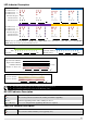
Summary
1. Once you choose to customize, all coefficients are configurable. However, you only have to setup as many as you need. Leave
the rest 0%.
2. Make sure you are clear about the definition of the positive and negative. Make sure you are also clear about the relationship
between the output quantity and motor rotation speed.
3. Usually, the coefficients of throttle and yaw are 100% or -100%. The rest of the coefficients should be decided by the proportion of
force arms of the motors.
4. The method introduced in this section is only suitable for central symmetry multi rotor.