
User manual

13 |
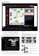
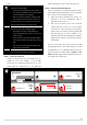
All slides should be in “Green” when all the sticks
are in the middle positions as showed in the top
figure. If not, power down your Tx and MC, wait
for 30s, and redo the same procedure.
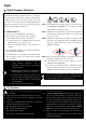
Notice:
Throttle: Slide left is craft down, slide right is craft up;
Rudder: Slide left is nose left, slide right is nose right;
Elevator: Slide left is craft back, slide right is craft
front;
Aileron: Slide left is craft left, slide right is craft right.
4. If the moving direction of the slide is opposite to the
description above, click the reverse button
[REV]/[NORM] beside.
If slides cannot go back to center points (turn green)
when you redo the calibration, just click [finish], then
slides will be at center automatically.
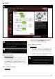
STEP4: Extra Control
This step is optional. X1 and X2 is for remote gain tuning;
X1 is also for gimbal pitch control. Setup the channel on
your RC correctly.
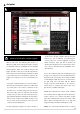
STEP5: Control Mode Switch
1. Whichever 2 or 3 positions switch/channel user has
selected or decided to use in the transmitter (for
control mode switching), in this case channel U
marking on main controller. At each switch position,
use sub-trim or end-point (+/-) fine tuning on your
transmitter, move the slider of channel U to GPS
(GPS Atti Mode), A (Atti. Mode), M (Manual Mode)
to turn the corresponding area blue respectively as
showed in the figure of last page.
Notice: To move the slider is to adjust sub-trim or
end-points of the channel selected.
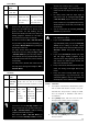
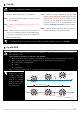
Tx
1 2 3
3 Position
Switch
TX
For 3-positions switch, you should assign:
Position-1 to Manual Mode;
Position-2 to Atti. Mode;
Position-3 to GPS Atti. Mode;
Or reverse the assignment for Position-1 and
Position-3.
For 2-positions switch, you can assign any
two of these three control modes as you like.
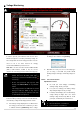
2. Move the slider to the range which reads Fail-Safe
MODE to turn the area blue, set Fail-Safe output of
receiver to input port-U. If you switch off your transmitter
now, the U channel slide should move to Fail-Safe MODE
and turn the corresponding area to blue. Otherwise please
reset the fail-safe.
Please refer to your RC manual for the details of
fail-safe setup.
1
Do NOT set the failed-safe position of throttle
under 10% endpoint.
2
MC would not execute Fail-Safe protection if you
don’t set it properly. You can verify the Fail-Safe
settings by shutting down your transmitter, and
then you can use the following method to check
whether MC is already in Fail-Safe mode.
Check the Assistant Software status bar at
the bottom side of the software
interface. Control mode will
change to Fail-Safe.
Check the LED indicator. Read the appendix
in this manual for details. LED will give blue
blinking if in fail-safe mode.