WooKong Multi Rotor User Manual Revision 1.9 Date: 18 October 2011 ® ® http://www.dji-innovations.com ©2010-2011 Dajiang Innovation Technology Co. Ltd. All Rights Reserved.
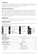
Copyrights This product and manual are copyrighted by Dajiang Innovation Technology Co. Ltd. with all rights reserved. No part of this product or manual shall be reproduced in any form without the prior written consent or authorization of Dajiang Innovation Technology Co. Ltd. No patent liability is assumed with respect to the use of the product or information contained herein. ©2010 Dajiang Innovation Technology Co. Ltd. All Rights Reserved.
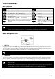
Package Items Main Controller (MC) The Main Controller (MC) is the brain of the system, it communicates with the IMU, GPS/Compass,ESC and RC transmitter to carry out autopilot functionality. The Main Controller provides USB interface to configure ×1 MC and update firmware from a PC (System requirement: Windows XP SP3 or 7) GPS & Compass LED Indicator IMU The GPS/Compass module is for sensing The LED indicates different states of The Inertial Measurement Unit the position and direction. system.
bottom during the flight, multi-rotor will descend; if you pull the stick to the bottom on the ground, it will cut motors in 3 seconds. However the slow spinning of motors will affect the flight performance, you’d better keep throttle stick position higher than 10% from cut-throttle during the flight! In Manual Mode it will cut motors when pull throttle stick under 10%.
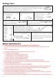
Ports Introduction Main Controller A E T R U X1 X2 X3 For roll control (left/right) For pitch control (front/back) For throttle control Or to gimbal roll servo For rudder control Or to gimbal pitch servo For Control Mode Switch For voltage monitor For D-Bus (S-Bus compatible) Or for gain tuning For gain tuning Or for gimbal pitch control M6 M5 M4 M3 M2 M1 F2 F1 To #6 rotor To #5 rotor To #4 rotor To #3 rotor To #2 rotor To #1 rotor To gimbal pitch servo Or to #8 rotor To gimbal roll servo Or to
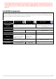
Mounting and Connection Note: Failure to follow any guidance outlined in this page will have severe consequence of your multi-rotor flight characteristic or worst crashing your multi-rotor or bodily harm. GPS/COMPASS (with Bracket): IMU: · · · · · · · · · · The IMU is best positioned near the multi rotor’s center of gravity, where vibration is relatively low.
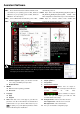
Assistant Software Software and Driver Installation STEP1: automatically, cancel it. Please download assistant software and driver from our website. If your operating system is 32bit, download STEP4: Open driver folder DJI_Wookong_M_Driver_32bit or 32bit driver; if your operating system is 64bit, download DJI_Wookong_Multi_Rotor_Driver_64bit, 64bit driver. Then decompress; Driver Setup.bat file and follow the steps to finish installation.
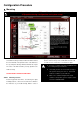
Configuration Procedure 1. Mounting For safety reasons, please disconnect ESCs and Power Connection Adapter or remove all propellers during configuration and system setup! Step 1 Step 2 STEP1: IMU Orientation gravity (C.G.) directly on the center plate. Fill in the Select IMU mounting orientation. Orient the IMU such that distance between body center of IMU/GPS and the C.G. the arrow marked on the printed surface of the IMU faces of multi rotor in X, Y & Z axles as showed in the figure.
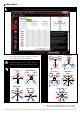
2. Motor Mixer For safety reasons, please disconnect ESCs and Power Connection Adapter or remove all propellers during configuration and system setup! Step 1 STEP1: 1 Mixer Type Hex-rotor Y Please make your selection according to your multi M6 rotor type.
software. If not, switch any of two wire connetcions of the incorrect motor. Customize This segment is reserved only for very special case, such as 3 customized airframe in non-conventional rotor Make sure the type of propeller matches the rotation arrangement. In the event, an airworthy multi-rotor craft direction of motor. with such rotor arrangement will require customized setting to meet WKM controller algorithm.
3. Tx Calibration For safety reasons, please disconnect ESCs and Power Connection Adapter or remove all propellers during configuration and system setup! Step 2 Step 1 Step 3 Step 4 Step 5 1 The transmitter you used must be Fail-Safe featured, which allows you to setup fixed outputs for U channel if the receiver lost signals, otherwise WKM will not enable the Fail-Safe. STEP1: 2 All the channels in your transmitter should be working independently: NO CCPM, NO channel MIX.
Normal Mode Manual push throttle stick over 10% in 3 seconds, otherwise motors will stop after 3 seconds. Atti. / GPS Atti. Mode 4. Mode Start Throttle stick under 10% will not stop motors in any control Throttle stick over 10%. mode. over 10%. Stop Throttle stick under 10%. During normal flight, only pull throttle stick Throttle 5. For safety reason, when the slope angle of stick The slope angle of under 10%, and multi-rotor is over multi-rotor is over 70° during the flight in Atti.
All slides should be in “Green” when all the sticks are in the middle positions as showed in the top 3 Position Switch figure. If not, power down your Tx and MC, wait 1 2 3 Tx for 30s, and redo the same procedure. Notice: Throttle: Slide left is craft down, slide right is craft up; TX For 3-positions switch, you should assign: Position-1 to Manual Mode; Rudder: Slide left is nose left, slide right is nose right; Position-2 to Atti.
4. Autopilot For safety reasons, please disconnect ESCs and Power Connection Adapter or remove all propellers during configuration and system setup! Step 1 Step 2 Step 3 STEP1: Basic Parameters adjusting the Tail Gyro. If you want fast stick reaction You must click [Default] button in first setup speed, increase the gain, otherwise decrease the gain. parameter, and subsequence firmware upgrade. However, the spin of multi-rotor is produced by the Usually, the default parameters are ready to go.
mode. advanced parameters to have a better fly experience. If you are a fresh player, you can tune the basic STEP3: parameters first as following. 1 2 Enhanced Failed-Safe Methods Increase the basic parameters 10% at a time so Choose one method for your failed-safe function, and the as to make your multi rotor hover or light oscillate method will be triggered when MC loses the control signal. after small angular command input.
5. Gimbal For safety reasons, please disconnect ESCs and Power Connection Adapter or remove all propellers during configuration and system setup! Step 1 Step 2 Step 3 Step 4 STEP1: Gimbal switch If you use gimbal, please choose On here. Adjust the reaction angle of automatic control. The initial value 100 is full angle. The bigger the gain the bigger the If you open the gimbal control in assistant software reaction angle.
6. Voltage Monitoring For safety reasons, please disconnect ESCs and Power Connection Adapter or remove all propellers during configuration and system setup! Step 1 Step 2 Step 3 Step 4 STEP1: you have just measured in the Calibration column of Protection Switch In order to prevent your multi-rotor from crash or other the dialogue box, and then click [Confirm]. harmful consequences caused by low battery voltage, we have designed two levels low voltage protections.
3 Loaded: Calculated, First level > Second level. Here the generation of Home Location is the Method of Acquiring Line Loss Voltage: same as the way used in Enhanced Failed-safe. 1 Make sure you can fly your multi-rotor normally Please refer to Enhanced Failed-safe in with a fully charged battery. Autopilot. 2 1 Use a fully charged battery, switch on the low Home. voltage protections in assistant software, and 2 observe the current voltage.
Flight 1. Digital Compass Calibration Why calibrate the compass? Calibration procedure: Ferromagnetic substances placed on multi rotor or around its working environment will affect the reading of earth magnetic 3 Position Switch for digital compass, it also reduces the accuracy of the multi 1 2 3 Tx rotor control, or even reads incorrect heading.
3. Test Fly Please does the test fly and gain tuning with Atti. Mode in the open air without heavy wind! Please refer to the first step of Autopilot in Configuration Procedure for the gain tuning. STEP1: Make sure your batteries are fully charged for your transmitter, MC and all the devices on your multi rotor; STEP5: Switch the system to Atti. Mode.
5. Quick LED Guide Read LED Indicator description in Appendix for the full details. or no light No light indicates Manual Mode. indicates control mode. , (You can ignore GPS indication.) indicates number satellites of the GPS indicates ATTI. mode. indicates GPS ATTI. mode. (You can ignore GPS indication.) Blinks three times indicate 4 GPS satellites are found. DO NOT take off. Blinks twice indicate 5 GPS satellites are found. Ready to go, but fly performance is not good.
Maintains Firmware Upgrade Please strictly follow the operation procedure for firmware upgrade, otherwise WKM might not work properly: 1. Make sure your computer is connected to the Internet. 2. Please close all the other applications during the firmware upgrade, including Anti-virus software and firewall. 3. Make sure the power supply is securely connected. DO NOT un-plug the power supply until firmware upgrade has finished. 4.
Appendix Customize Motor Mixer For a multi rotor, the roll, pitch, yaw and vertical axes are contributed by the combination of rotors’ outputs. This procedure is called Mix Control. The proportion of rotors’ outputs is decided by the mechanical structure. Customers can setup the motor output coefficients C in [Motor Mixer] [Customize] so as to realize the Mix Control. Before customization, you should have the important knowledge following: 1. Motor output = C × Stick position (A or E or T or R).
(𝐶𝑇1 + (𝐶𝑇1 { (𝐶𝑇2 𝐶𝑇3 + 𝐶𝑇5 ) × 𝑇 = + 𝐶𝑇2 ) × 𝑇 × 𝑎 = (𝐶𝑇2 (𝐶𝑇4 + 𝐶𝑇4 + 𝐶𝑇6 ) × 𝑇 (To keep yaw direction balance) + 𝐶𝑇5 ) × 𝑇 × 𝑎 (To keep pitch direction balance) 1 + 𝐶𝑇4 + 2𝐶𝑇3 ) × 𝑇 × 𝑑 = (𝐶𝑇1 + 𝐶𝑇5 + 2𝐶𝑇6 ) × 𝑇 × 𝑑 (To keep roll direction balance) As we defined before: Pull stick T<0, multi-rotor moves down; Push stuck T>0 multi-rotor moves up, we can choose the following setup: Hex-rotor V 100% M2 100% M1 d 2d 100% 100% M3 M4 100% M6 a Yaw Axis Pitch Axis a Front 100% Roll Axis
(𝐶𝐸1 + 𝐶𝐸2 (𝐶𝐸1 + { (𝐶𝐸2 + 𝐶𝐸3 + 𝐶𝐸4 + 𝐶𝐸5 + 𝐶𝐸6 ) × 𝐸 = 0 (To keep throttle direction balance) 𝐶𝐸3 + 𝐶𝐸5 ) × 𝐸 = (𝐶𝐸2 + 𝐶𝐸4 + 𝐶𝐸6 ) × 𝐸 (To keep yaw direction balance) 3 + 𝐶𝐸4 + 2𝐶𝐸3 ) × 𝐸 × 𝑑 = (𝐶𝐸1 + 𝐶𝐸5 + 2𝐶𝐸6 ) × 𝐸 × 𝑑 (To keep roll direction balance) Also proportion of coefficients of the motors at the same side of pitch axis should be equal to the proportion of force arms of those motors: 𝐶𝐸1 ∶ 𝐶𝐸2 = 𝐶𝐸4 ∶ 𝐶𝐸5 = 𝑎: 𝑎 = 1: 1.
LED Indicator Description Manual Mode Tx Signal Lost GPS satellites found < 5 GPS satellites found < 6 GPS satellites found < 7 Attitude & GPS good *All OFF Attitude status fair Attitude status bad 0 1 2 s 3 0 1 GPS Atti. Mode 2 3 s 3 s Atti.
Product Specifications General specifications Built-In Functions: Autopilot Enhanced Fail Safe Low Voltage Protection S-Bus Receiver Support Multi Rotor Types: Quad-rotor I, X; Hex-rotor I, V, Y, IY; Octo-rotor X, I, V. Supported ESC output: 400Hz refresh frequency Recommended Transmitter: PCM or 2.