Ground Station Wireless Data-link User Manual V 2.2 www.dji-innovations.
Disclaimer Please strictly follow these steps to install all the hardware and software products. Dajiang Innovations Technology Co. Ltd. assumes no liability for damage(s) or injured incurred directly or indirectly from the use of this product.
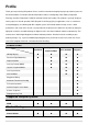
Profile Thank you for purchasing DJI product. Please read this instruction thoroughly for proper operation of your new DJI Ground Station. Full featured DJI Ground Station enables 3-D Map Way Points Editing, Flight Path Planning, Real-time Flight State Feedback and Auto Takeoff and Landing. This product is specially designed for the purpose of aircraft operation, BVR (Beyond Visual Range) flying in applications such as surveillance, aerial photography, etc.
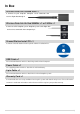
In Box Wireless Data-link Ground End ×1 It connects to your computer. Computer sends commands and receives flight data through it. Wireless Data-link Air End 900MHz ×1 or 2.4GHz ×1 It connects to DJI autopilot system. Autopilot system sends flight data and receives commands from computer by it. Ground Station Install CD ×1 It contains Ground Station and all required software installation files.
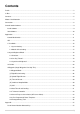
Contents Profile........................................................................................................................................................... 3 In Box........................................................................................................................................................... 4 Contents.......................................................................................................................................................
Troubleshooting .....................................................................................................................................38 Data-link LED Introduction ......................................................................................................................41 Wireless Data-link Specification ..............................................................................................................
Matters Need Attention 1. The ability of penetrating of radio signal from 2.4GHz wireless data-link is weak, please make sure the antenna of it is always visible to the ground end during the flight. Human body, trees, buildings or hills will stop the communication between air end and ground end. 2. You‟d better put the ground end at high place. This can guarantee a good communication range. 3. Make sure the antenna head of air end is erect down, and the antenna head of ground end is erect up.
Connection Normal connection with Ace, WKM autopilot system Ground End · You should have a DJI Ground Station installed laptop · Use the USB cable supplied by us to connect the ground end to you laptop. One end of the USB cable has two heads, make sure both of them are plugged into your laptop.
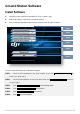
Ground Station Software Install Software Operating system requirement: Windows XP, Vista, 7 (32-bits only); Adobe® Reader® is required for user manual reading; Please follow the following install procedure strictly to install all required software. Step 1 Step 2 Step3 Step 4 Step 5 Step 6 Insert the CD to CD-ROM, auto-run window will appear. STEP1: Check if .Net Framework 3.5 has been installed. If not, click Install .Net Framework 3.5 to install. If yes, go to step 2.
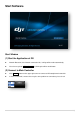
Start Software Start Window (1) Start the Application of GS Network Detection, if the Network connection fails, it will go offline mode automatically. You also can go into OFFLINE MODE by clicking the offline mode button. (2) Connect to Main Controller Click Connect button on the upper right corner to connect to DJI autopilot main controller. If errors are showed, it means there may be some problem on connection, please check.
Application Control Mode Switch Pa u m se t Joystick Keyboard W i ssi h e Mode Mode on ith J Ke o y s yb tick Re oa a rd ctiv mi sum ss co e io e nt of ro us n the l e Tx Switch Tx Switch Manual Mode GPS Cruise Mode h Sw itc Tx Signal Lost 1st Line Protection R/C MAN Tx Signal Resume Tx Signal Resume If Tx Signal Resume Atti.
GUI 1 2 4 3 5 7 6 20 8 9 10 25 11 12 13 14 15 16 18 24 17 23 19 22 21 10 26 28 27 29 30 31 32 GUI Instruction 1. 2. 3. Joystick: Stick: Choose your input equipment. Choose Calibration: Joystick calibration. Channel Mapping: Joystick channel mapping. ToolBox: Click Go Mode: A real-time single waypoint function. F_Channel Controller: Customize F channels‟ function of Main Controller.
4. 5. Target Line: Line between aircraft and current target. Data Link Setting: The waypoint number of one package. Upload one package. Retry one package timeout. Language(语言): Click to change language, English or Chinese. 中文. English. Help: Check for Update: Update software here. About: Check your DJI Ground Station version here. 6. Enter location: Go to the location of your input. 7. Fly Trace: Click to show the trace of aircraft. 8.
29. MODE: Real-time control mode. 30. Other state parameters: Decided by the autopilot system you WKM: Motor Voltage: Battery voltage; Ace: Servo Voltage: Servo output voltage; Pitch: Real-time pitch percentage. Throttle: Real-time throttle percentage. 31. Download and upload progress bar. 32. Cancel: Cancel button.
1 View Mode STEP1: Check Signal Strength: shows no communication between GS and MC, please check Troubleshooting in Appendix. Otherwise communication is constructed, can go to next step. STEP2: Find Aircraft: Shows LATI, LONGI and ALTI of aircraft, then the aircraft logo will be showed on the map. STEP3: Altitude Off Set: Click Altitude Off Set,you can just use the value recommended, and click OK. Read the paragraph below to get more details.
Click DEFAULT to retrieve default parameters. The system setting includes both Basic Setting and Data Link Setting. Basic Setting Sound: If switch on, there will be alarm sound when the radio signal is bad; Instrument Board Style: Choose different instrument board style; Action Setting: Set action number display mode.
1.2 Altitude Offset Setting GIS database (Google Earth™) is not precise, while Flight Path Mountain and other obstacle/building collision checking feature performed based on this database, which is not real-time or up-to-date. Google Earth™ plug-in is only for the purpose as a general landscape browser, for quick way points positioning without much safety guarantee. Pressure sensor is used for altitude sensing, leading the result varies according to weather.
2 Joystick/Keyboard Mode Joystick/Keyboard mode is the 2nd permission for users, and Fly Simulation, One Key Takeoff and Joystick/Keyboard functions can be operated. 2.1 Simulator Our system support Pre-Flight Simulation aims to help you getting familiar with the Ground Station software.
"Auto Takeoff failure, the aircraft is already flying!" "Auto Takeoff failure, please switch to auto mode!" 2.3 Joystick and Keyboard Click Pause, choose joystick or keyboard mode, Fig.① shows that keyboard is chosen, and then key board will be used to control the aircraft. Fig① Keyboard Mode The keys W, S, A, D, ↑, ↓ and ←, → are used to control the aircraft. W、S for Pitch, A, D for Roll, ↑, ↓for A W S → D → Throttle and ←, → for Rudder.
Connection Joystick Choose Joystick Refer to the user manual of the specific controller / Joystick you choose, and ensure the USB cable is properly connected. Please Notices: ENSURE the Joystick is properly connected physically, do not disconnect the joystick connection when Joystick Mode is activated.
figures below. Where the „+‟ represents positive channel value, „-‟ represents negative channel value. (Fig②) Push your joystick, and the channel value feedback will tell whether it matches with our suggested joystick control direction or your own settings, and then make your adjustments. For Type 1 controller, please refer to the controller‟s manual.
3 Click Go Click Go Mode is a real-time single waypoint flight mode. Under this mode, you can send a waypoint to your aircraft immediately. STEP1: Make sure your aircraft is already flying in GPS Atti. or GPS Cruise Mode. STEP2: Click Tool Box Click Go Mode to open the window as the figure shows. STEP3: Click Enter Click Go Mode. Now your aircraft will go into hovering station.
4 Waypoint (Single Waypoint User Skip This) Waypoint package includes Waypoint Mode, Auto Take offing/Landing, F Channel Controller, General Purpose Servo Action, 6 Pre-Programmed Route Templates and Photogrammetry Tool. 4.1Waypoint Mode See the flow chart to get the information about Waypoint mode operation.
Instructions 1) LOG to print info. Such as: upload success, upload failed… 2) Waypoint list: you can click the yellow icon to select the waypoint properties in the table. 3) You will see Mission properties if14) selected. Mission properties Mission Time Lmt: If the flight-time exceeds the value (>=60sec), it will automatically go home. Route: The selection of mission execution mode: includes both modes of Start_to_End and Continuous.
TurnMode: Set the turn mode individually. Forward_Flight_Speed: Velocity from previous point to current point which is limited to <= 25 m/s. 13) HeadingDegree: Heading degree facing this way point, unit in degree. HoldTime: The time to stay at this way point, unit in second. Waypoint Action properties Period: (Unit: second) Setting the time period of the action. RepeatTime: Setting the repeat time of the action assigned.
(I)Flight Mission Setting STEP1: Click STEP2: Click New to edit a new mission. STEP3: Add way points. to open the mission editor, see fig.①. Fig① Add way points There are two way on adding way points. A maximum of 200 way points can be added in the Ace waypoint mode. The waypoint will change to be green if selected, see fig.②. 1) Fig② Add Point by Point STEP1: Click +,or press Ctrl。 STEP2: Left click on the 3D-Map where the locations you want to add a way point.
Waypoint Properties Editing Select the way point in 3D-Map or in the Editing Mission Menu. See figure as following, altitude, TurnMode, Forward Flight Speed, HeadDegree and HoldTime can be set, then press Enter to confirm. (1) (2) (3) (4) (5) (1)Altitude The altitude (unit m), if pointed to height mode, means relative height; otherwise altitude mode means the waypoint altitude. Edit the altitude of each way points by clicking the Altitude Calibration.
Click Editing Mission then you can see the figure shown as following, MissionTimeLmt, Route selection, StartWayPoint and VerticalSpeedLimit can be set, and press Enter to confirm. (1) (2) (3) (4) (5) (1)MissionTimeLmt If the aircraft‟s flying time exceeds the value, it will Type in precise time at MissionTimeLmt in the automatically go home. (Default value is 65535sec.Min Mission Properties. value is 60sec, Max value is also 65535sec.) (2)Route Selection route modes: Start_to_End or Continuous.
Examples for Way Point turning mode: shown as figure A1/A2 as following. Examples for Mission/Way Point properties setting: B1/B2Selection for the state of Route, and StartWayPoint. Way point 1: Bank_Turn Way point 1: Stop and Turn Adaptive_Bank_Turn 0 1 0 1 Bank_Turn: The aircraft will keep the speed when turning, so it will deviate from its route. Adaptive_Bank_Turn: The aircraft will slow down so as to follow the route.
(II) Upload Flight Mission Final Check & Mission Transmitting: Click UPLOAD on the upper bottom of the Mission Editor to send flight mission to DJI Autopilot main controller. Here a mission review table as following example will appear for mission final check. Press OK to confirm, after successfully synchronized, the mission is ready to be executed.
Tips: While a mission is in process, you can still re-edit your mission by using EDIT. Please click EDIT in mission editor to do so.Then the mission editor will return to the state as explained in previous section Flight Mission Setting While a mission is in process, you can pause the mission by using PAUSE function. Please click PAUSE, and the aircraft will slow down and stay hovering. Then click CONTINUE the aircraft will resume the un-finished mission.
Auto Landing After completing the mission or when the aircraft returns home, hovering above within visual contact. Use ground station keyboard for auto landing (Press pause button then select keyboard control). Auto Landing button will be available. Use W/S (Pitch), A/D (Roll), ↑/↓(Throttle) and ←/→(Rudder) to navigate to decent landing zone, or allowing Ground Station to decent automatically provided the landing zone is clear of any obstacles. Then you can use ↓ to land your aircraft.
4.4 General Purpose Servo Action (GP-Servo Action) GP-Servo Action is supported by one of the servo output channels in the transmitter, which will work as an interface between DJI Autopilot system and your external devices. This feature allows DJI autopilot to operate your external devices automatically during basic aircraft waypoint mission, as explained in previous sections.
One GP-Servo Action Cycle Initial Position GP-Servo Action Begin GP-Servo ActionDone STEP1 Position STEP2 Position HOLD ON 1s 2 D 05:50 Way point 1 GP-Servo Period Repeat Time Start Delay Repeat Distance 06:40 06:25 06:20 06:15 1 HOLD ON 1s HOLD ON 1s GP-Servo Action during flight mission s Y5 EL A STEP3 Position 06:10 06:05 5s : : : : 5s 5 5s 0 Way point 2 GP-Servo Period Repeat Time Start Delay Repeat Distance : : : : 0 0 0 40 3 40m Way point 40m 40m GP-Servo Action Cycle D
STEP3: The result is shown as Fig.②. Route Template explanation: You can add more than one area which can be moved. You can click the area to select or unselect the area. Green area means the area is selected. You can delete the area or generate the points only when the area is selected. Click the line template or scan template button twice, the Route waypoints will be assigned vertically or horizontally. You can move the mouse over the parameter input box to get meaning of the parameter.
4.6 Photogrammetry Tool Photogrammetry tool is for the user who wants to create the professional maps by aerial photography easily. In order to do that, you just need to setup the servo action and mission path correctly as follows. Tips: This tool is actually a functions combination. It simplifies the parameters setup procedure for the aerial photography. You can still setup all the tools introduced before individually for your aerial photography, however that will be very complicated.
Appendix List of Ground Station Shortcut Keys Operation Function View Mode Left Key+ ↑, ↓, ←, → Left Key+ Up/Down/Left/Right to move the map Up/Down/Left/Right to move the map Up/Down/Left/Right to rotate the map Ctrl + Mouse Roll Up, Ctrl +Mouse Roll Down Left/Right to rotate the map Shift + Mouse Roll Up, Shift + Mouse Roll Down Up/Down to rotate the map Double click Left Key or Mouse Roll Up Zoon In the Map Double click Right Key or Mouse Roll Down Zoon Out the Map Joystick/Keyboard Mode Ctr
Troubleshooting Ground Station Launching Failure Map loading failure and abort Solution: Choose “run as administrator” when you right click the Ground Station icon in Windows 7 In English version Windows XP, if customer cannot open the program and the following error is reported: system format exception.
Fig① Fig② Ground Station Software Crash Ground Station Software Crash will not affect the aircraft under mission execution. The aircraft will keep going on the flight mission edited even the Ground Station Software crash. The Ground Station Software can be launched again, but loss of the following information will happen: Altitude Offset value, Aircraft tracks and Way points.。 Solution: Click on the DOWNLOAD button, to retrieve the previously set way points from the DJI Autopilot main controller.
Please ensure it is under the Autopilot Mode or Waypoint Mode. The action will not be valid unless the value of “hold time” is more than one second. When Wireless Data-Link Doesn’t Work… If your Ground Station cannot be connected with the main controller, please check the following issues. Solution: Make sure you have installed radio driver. If the Antenna is broken, the communication distance cannot be guaranteed. Two Wireless Data-Link Terminals had been placed too close.
Data-link LED Introduction Function Introduction LINK-ALARM Distance Alarm Light on indicates distance warning. LINK-ALARM Network Light Light on indicates communication is on with air end. DATA-POWER Power Light Light on indicates working well. DATA-POWER Data Light Light flash indicates data transmit and receive. Link Data Light Light on indicates communication is on. Power Power Light Light on indicates working well.
Wireless Data-link Specification 2.4GHz 900MHz Performance RF Data Rate 700kbps 100kbps Indoor/Urban Range ≤500m ≤1Km Outdoor/RF Line-of-Sight Range ≤3km ≤10Km Transmit Power 130mW 1000mW Receiver Sensitivity (1% PER) -95dBm -110dBm Ground end: 460mW Ground end: 1600mW Air end: 460mW Air end: 1500mW Frequency Band 2.
Ground Station / Wireless Data-link ©2010-2011 Dajiang Innovation Technology Co. Ltd. All Rights Reserved. 6/F, HKUST SZ IER Building, No.9, Yuexing 1st Rd., South District, Hi-Tech Park, Shenzhen, 518057, Guangdong, China Tel: 0086-755-2665-6677 Sales ext: 201, 202, 203 Fax: +86-755-8306-7370 Service hotline: +86-755-2267-3777 Sales: sales@dji-innovations.com Technical support: support@dji-innovations.com Others: info@dji-innovations.com Google logo is a registered trademark of Google Inc.