
User manual

15
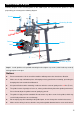
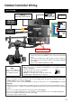
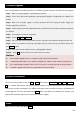
Gimbal Controller Wiring
GCU Wiring
Gimbal Controller (GCU)
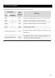
RC Receiver
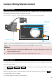
· These are example connections. Prepare 2 TXs, one is for gimbal control, the other one for aircraft control, refer to
2-Pilots Solution for more detail in Appendix.
· If one receiver is used for aircraft and gimbal control at the same time, refer to 1-Pilot Solution for detail in
Appendix.
· Setup Aileron, Elevator, Rudder channels on gimbal control TX. Command stick stands for gimbal rotation velocity,
center position is for 0,endpoint for maximum velocity(both clockwise and counter clockwise directions). (End Point
is 100%)
· Choose one 3-position switch/channel as Z15 working modes switch.(MODE)
· Choose one 2- position switch/channel as camera shutter control switch(SHUT), also one for HDMI switch(AUX1).
· Please refer to WKM User Manual for aircraft control setting.
· Connect the receiver to GCU correctly.
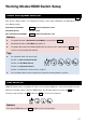
Battery
· Connect the XT60 to the GIMBAL on the center frame if DJI S800
used.
· Attention that S800 power supply voltage should be within the
defined limits (6S), when using one battery for both S800 and Gimbal
power supply.
· Please refer to S800 User Manual for details.
Battery
(4S~12S)
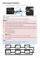
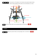
· Make sure ports are accessible when installing MC so as to facilitate wiring and
software configuration.
· In 3-pin ports, pins near the nicks are signal pins.
· 6-pin cable for G6, 8-pin cable for G8.
· DO NOT cover the heat sinks, keep them unobstructed.
· The IMU module is NOT water-proof or oil-proof.
Wireless Video
Transition Module
Air End
WKM
Please refer to WKM User
Manual for all connection
and configuration details.
WKM
Any spare CAN port on
DJI autopilot system
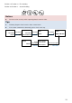
RC Receiver
(Aircraft control)
G8
G6
Or
RC Receiver
(Futaba
/ Hitec)
7
1
2
4
RC Receiver
(JR)
AUX2
RUDD
ELEV
AILE
2-Position Switch
2-Position Switch
2-Position Switch
2-Position Switch
8-Channel
8-Channel
USB Port
PC connection for configuration and
firmware upgrades with an USB cable.
Heat
Sinks
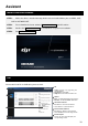
Ensure the side with copper
contacts is face upward.